


Operation
6 309921N
Operation
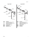
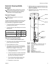
Model 234401, Series D
1. Attach air hose(s) to air regulator outlet valve
289165.
2. Attach air hose to main shut-off valve 288798.
3. Open main shut-off valve 288798.
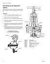
4. Turn the T-hand adjusting screw in or out to adjust
regulator to desired setting.
5. Open outlet valve 289165 to supply air to spray
guns or tool.
6. With air flowing, readjust air pressure regulator if
necessary.
7. Turn off unit when not in use. Follow Pressure
Relief Procedure, page 8.
Model 24M178, Series B
1. Attach air hose(s) to outlet elbow fitting 120375.
2. Attach air hose to inlet elbow fitting C19024.
3. Open main shut-off valve 288798.
4. Turn off unit when not in use. Follow Pressure
Relief Procedure, page 8.
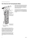
Automatic Drain
The automatic drain is equipped with a float actuated
device which automatically ejects liquid contaminates
under pressure.
Coalescer Pressure Drop Indicator
The differential pressure drop indicator provides early
detection of a clogged coalescing filter element. As the
filter element becomes clogged, the red indicator starts
to rise while air is flowing through the unit. When the
pressure drop across the element reaches 10-12 psi
(69-83 kPa, 0.7-0.8 bar), the red indicator will be in full
view, and the element should be replaced. Failure to
replace the element when the pressure drop exceeds
10 psi (69 kPa, 0.7 bar) will affect your air quality and
tool efficiency.
WARNING
Do not exceed the Maximum Incoming Air Pressure
of the equipment. Over pressurizing can cause
component rupture and serious injury.