


Installation
309921N 3
Installation
1. Before installing air line components, blow out the
pipe line to remove debris. Be sure air to the regula-
tor is clean. Erratic operation or loss of regulation is
usually caused by dirt in the regulator.
2. Install the Air Drying System as close as possible to
the equipment it serves. Use template 289185, pro-
vided, to position system.
3. Install air shut-off valve 288798 upstream from the
air system to isolate it for service.
4. Install system so air flows through filters in the direc-
tion noted on top of filter.
5. A minimum 1/2 in. npt piping is recommended.
Avoid using too many fittings, couplings, etc., which
will restrict air flow.
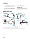
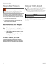
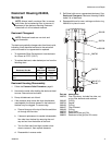
Shop Air Piping Layout
2
4
6
8
1
1
1
1
2
4
6
8
1
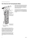
SATURA
TED
NORMA
DESICCANT
¨
2
4
6
8
1
1
1
1
2
4
6
8
1
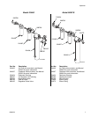
Membrane air
drying system
Desiccant air
drying system
Ball Valve
Drain Valve
Drain
Leg
Air Control unit
or Air Filter
1/2 in.
(13 mm) drops
Main Air Line
3/4 in. (19 mm) minimum
1-1/4 in. (32 mm) optimum
S
l
o
p
e
s
d
o
w
n
a
n
d
a
w
a
y
R
e
c
o
m
m
e
n
d
e
d
4
i
n
.
(
1
1
7
m
m
)
d
r
o
p
i
n
5
0
f
t
(
1
5
.
2
4
m
)
g
a
l
v
a
n
i
z
e
d
p
i
p
e
r
e
c
o
m
m
e
n
d
e
d
)
Coalescer
Air
Filter
Compressor
Flexible hose
between compressor
and stand pipe
1
5
-
2
0
f
t
.
(
4
.
6
-
6
.
1
m
)
• Main Air Line stand pipe should not be smaller than compressor outlet size.
• A minimum of 25 ft. (7.62 m) from compressor to first filter outlet is required to cool air [50 ft. (15.24 m) optimum]
OR
Main Air
Shut-off Valve