


5 ELECTRICAL CONNECTION
INFORMATION
4
Installation Instructions
• DO NOT USE AN EXTENSION CORD OR AN
ADAPTER PLUG WITH THIS APPLIANCE.
Dryer must be electrically grounded in accordance with
local codes and ordinances, or in the absence of local
codes, in accordance with the NATIONAL ELECTRI-
CAL CODE, ANSI/NFPA NO. 70.
WARNING - TO REDUCE THE RISK OF
FIRE, ELECTRICAL S HOCK, AND PERSONAL
INJURY:
ENSURE PROPER GROUND EXISTS BEFORE USE.
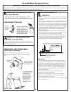
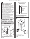
ELECTRICAL REQUIREMENTS
This appliance must be supplied with 120V, 60Hz, and connected
to a properly grounded branch circuit, protected by a 15- or 20-
amp circuit breaker or time-delay fuse. If electrical supply provid-
ed does not meet the above specifications, it is recommended that
a licensed electrician install an approved outlet.
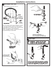
IF LOCAL CODES PERMIT,
AN EXTERNAL GROUND WIRE
(NOT PROVIDED), WHICH MEETS
LOCAL CODES, MAY BE ADDED
BY ATTACHING TO THE GREEN
GROUND SCREW ON THE REAR
OF THE DRYER, AND TO A GROUNDED
METAL COLD WATER PIPE OR OTHER
ESTABLISHED GROUND.
WARNING - THIS DRYER IS EQUIPPED
A THREE-PRONG (GROUNDING) PLUG FOR
YOUR PROTECTION AGAINST SHOCK
HAZARD AND SHOULD BE PLUGGED
DIRECTLY INTO A PROPERLY GROUNDED
THREE-PRONG RECEPTACLE. DO NOT CUT
OR REMOVE THE GROUNDING PRONG
FROM THIS PLUG.
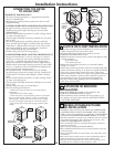
EXHAUST SYSTEM CHECK LIST
HOOD OR WALL CAP
• Terminate in a manner to prevent back drafts or entry of birds or
other wildlife.
• Termination should present minimal resistance to the exhaust air flow
and should require little or no maintenance to prevent clogging.
•Never install a screen in or over the exhaust duct.
This could cause lint build up.
• Wall caps must be installed at least 12 in. above ground level or any other
obstruction with the opening pointed down.
SEPARATION OF TURNS
For best performance, separate all turns by at least 4 ft. of straight duct,
including distance between last turn and exhaust hood.
TURNS OTHER THAN 90º
• One turn of 45º or less may be ignored.
• Two 45º turns should be treated as one 90º turn.
• Each turn over 45º should be treated as one 90º turn.
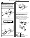
SEALING OF JOINTS
• All joints should be tight to avoid leaks. The male end of each section of
duct must point away from the dryer.
• Do not assemble the ductwork with fasteners that extend into the duct.
They will serve as a collection point for lint.
• Duct joints can be made air and moisture-tight by wrapping the
overlapped joints with duct tape.
• Horizontal runs should slope down toward the outdoors ½inch per foot
INSULATION
Duct work that runs through an unheated area or is near air conditioning
should be insulated to reduce condensation and lint build-up.
6 EXHAUST INFORMATION
WARNING - IN CANADA AND IN THE UNITED
IS 4 IN (102mm). DO NOT USE DUCT LONGER
STATES, THE REQUIRED EXHAUST DUCT DIAMETER
THAN SPECIFIED IN THE EXHAUST LENGTH TABLE.
Using exhaust longer than specified length will:
• Increase the drying times and the energy cost.
• Reduce the dryer life.
• Accumulate lint, creating a potential fire hazard.
The MAXIMUM ALLOWABLE duct length and number of
bends of the exhaust system depends upon the type of duct,
number of turns, the type of exhaust hood (wall cap), and all
conditions noted below. The maximum duct length for rigid
metal duct is shown in the table below.
The correct exhaust installation is YOUR RESPONSIBILITY.
Problems due to incorrect installation are not covered
by the warranty.
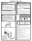
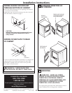
EXHAUST LENGTH
4" DIA.
4"
4" DIA.
4" DIA.
2-1/2"
RECOMMENDED MAXIMUM LENGTH
Exhaust Hood Types
Recommended
No. of 90º
Elbows
Rigid
Metal
Rigid
Metal
90 Feet
60 Feet
45 Feet
35 Feet
0
1
2
3
60 Feet
45 Feet
35 Feet
25 Feet
Use only for short
run installations
Remove and discard existing plastic or metal foil transition
duct and replace with UL listed transition duct.