


Installation Instructions
1 PREPARING FOR INSTALLATION
OF NEW DRYER
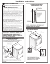
Minimum Clearance Other Than Alcove or Closet Installation
Minimum clearance to combustible surfaces and for air opening are: 0 in. clearance both sides and 1 in. rear. Consideration
must be given to provide adequate clearance for proper operation and service.
2 GAS REQUIREMENTS
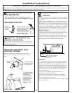
DISCONNECTING GAS
The use of old flexible connectors can cause leaks and
personal injury. Always use new flexible connectors when
installing gas appliances.
WARNING - NEVER REUSE OLD
FLEXIBLE CONNECTORS.
2
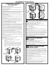
TILT THE DRYER SIDEWAYS
AND REMOVE THE FOAM
SHIPPING PADS BY
PULLING AT THE SIDES
AND BREAKING THEM
AWAY FROM THE DRYER
LEGS. BE SURE TO
REMOVE ALL OF THE
FOAM PIECES AROUND
THE LEGS.
•
Installation must conform to local codes and ordinances,
or in their absence, the NATIONAL FUEL GAS CODE,
ANSI Z223.
• This gas dryer is equipped with a Valve & Burner Assem-
bly for use only with natural gas. Using conversion kit
WE2 5X0217, your local service organization can convert
this dryer for use with propane (LP) gas. ALL CONVER-
SIONS MUST BE MADE BY PROPERLY TRAINED
AND QUALIFIED PERSONNEL AND IN ACCOR-
DANCE WITH LOCAL CODES AND ORDINANCE
REQUIREMENTS.
• The dryer must be disconnected from the gas supply
piping system during any pressure testing of that system
at a test pressure in excess of 0.5 PSI (3.4 KPa).
• The dryer must be isolated from the gas supply piping
system by closing the equipment shut-off valve during
any pressure testing of the gas supply piping of test
pressure equal to or less than 0.5 PSI (3.4 KPa).
WARNING
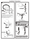
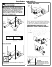
DRYER GAS SUPPLY CONNECTION
2"
2-5/8"
3/8" NPT MALE THREAD GAS SUPPLY
NOTE: Add to vertical dimension
the distance between cabinet
bottom to floor.
GAS SUPPLY
• A 1/8-in.National Pipe Taper thread plugged tapping,
accessible for test gauge connection, must be installed
immediately upstream of the gas supply connection to
the dryer. Contact your local gas utility should you have
questions on the installation of the plugged tapping.
Supply line is to be 1
• You must use with this dryer a flexible metal connector
/2-in. rigid pipe and equipped with
an accessible shut-off within 6 ft. of, and in the same
room with the dryer.
•
•
Use pipe thread sealer compound or Teflon tape
appropriate for natural or LP gas.
listed connector ANSI Z21.24 / CSA 6.10. The length of
the connect shall not exceed 3 ft.
•
•
Connect flexible metal connector to dryer and gas supply.
Open shut-off valve.
TIP: Install your dryer before installing your washer.
This will allow better access when installing dryer exhaust.
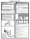
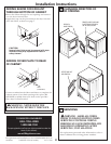
REMOVING LINT FROM WALL
EXHAUST OPENING
INTERNAL DUCT
OPENING
CHECK THAT EXHAUST
HOOD DAMPER OPENS
AND CLOSES FREELY.
WALL
Remove and discard existing plastic or metal foil
transition duct and replace with UL listed transition
duct.
•
DISCONNECT AND DISCARD OLD
FLEXIBLE GAS CONNECTOR AND
OLD TRANSITION DUCTING
MATERIAL. REPLACE WITH NEW
CSA(AGA) APPROVED FLEXIBLE
GAS LINE CONNECTOR AND UL
APPROVED TRANSITION DUCT.
TURN GAS
SHUT-OFF VALVE
TO THE OFF
POSITION.