


13
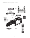
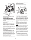
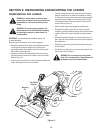
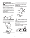
• By SLIGHTLY moving the implement control lever in the vari-
ous directions, check that all control lever positions correctly
operate the loader movements as indicated in Figure 10.
IMPORTANT: Move the control lever only slightly.
Figure 10
• If loader movements do not respond correctly, turn the
tractor’s engine off, set the parking brake and recheck all
hydraulic connections. Loader control movements must be
correct before proceeding.
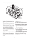
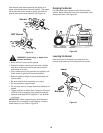
Initial Installation of Loader on Tractor
The control lever will be used to aid in mounting the loader to the
tractor. To complete the initial installation, proceed as follows:
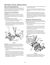
NOTE: If an overhead lift was used and the pistons of the two
bucket cylinders have not been connected to the bucket rear
mounting brackets as instructed earlier, use the tractor’s imple-
ment control lever to extend the pistons as needed to connect the
cylinders now.
• If an overhead lift was used to position the loader, lower the
lift to make certain it is no longer supporting the loader. Do
not remove the attaching devices yet. Re-start the tractor
engine.
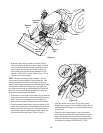
• While observing the base of the masts, slowly push the imple-
ment control lever forward to lower the boom, and to the right
to dump the bucket. Drive the tractor forward (as needed)
to settle the masts onto the tubular bars of the RH and LH
mounts. Refer to Figure 11.
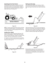
• Continue to carefully extend the boom cylinders (and roll back
the bucket if necessary) until the center points of the support
plates on the bottom of the loader hitch bracket at the front of
loader hitch arms are resting on the ground (Refer to Figure
13). The support plates and bucket should be supporting the
loader and the bottom of each mast should now be higher
than the tubular bars of the loader mounts.
• Stop the tractor engine and engage the parking brake.
Disconnect the loader hoses from the hydraulic couplers
by pushing inward the locking collars of the tractor’s female
hydraulic couplers.
• Start the tractor and drive to the rear of the front loader. Align
with the opening between the loader masts, and slowly drive
the tractor forward while guiding the bottoms of masts into
the RH and LH mounts.
• Stop the tractor engine and engage the parking brake.
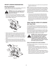
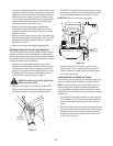
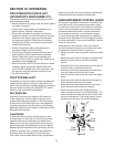
Checking Implement Control Lever Operation
The tractor’s implement control lever is used to control the move-
ments of the loader. Perform the following test to make certain
that the loader hydraulic hoses and tubes are correctly connected.
All implement control lever movements should result in the loader
movements described in this sub-section.
• Using the color coded plugs and matching color coded
washers on the loader hoses to guide you, remove the plugs
and connect each loader hose to the appropriate hydraulic
coupler. If for any reason the color coded plugs of the outlets
and/or washers of the hoses are unavailable or incorrect,
refer to the hose routing information on page 12
WARNING: Always comply with all Safety Rules
before starting the tractor.
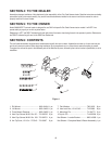
• Start the tractor’s engine and operate at a low/safe RPM.
• Shift the tractor’s hydraulic lock lever to the center position.
See Figure 9 and refer to the tractor Operator’s Manual.
Figure 9
Hydraulic
Lock Lever
Dump
Bucket
Lower
Boom
Boom
Float
Boom
Raise
Roll Back
Bucket