


12
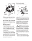
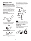
Figure 7
• Stop the tractor engine and set the tractor’s parking brake
before leaving the operator’s seat. Proceed to “Installing the
Front Loader” in this section.
Pre-Charging Cylinders for Initial Installation
If an overhead lift is not available, the front loader cylinders can be
used to position the loader for installation. To position the loader,
proceed as follows:
• Start the tractor and carefully drive the tractor to position it
along the right side of the front loader, facing in the opposite
direction of the loader.
IMPORTANT: Stop the tractor engine. Set the tractor’s parking
brake before leaving the operator’s seat.
• Remove the four protective caps from the male couplers at
the free ends of the hydraulic hoses.
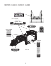
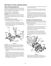
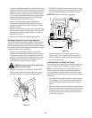
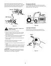
• Locate the color coded protective plugs in the female
hydraulic couplers on the lower right side of the tractor, just in
front of the right/rear tire. Refer to Figure 8.
• Using the color coded plugs and matching color coded
washers on the loader hoses to guide you, remove the plugs
and connect each loader hose to the appropriate hydraulic
coupler. Refer to Figure 8.
NOTE: If for any reason the color coded plugs of the outlets
and/or caps and washers of the hoses are unavailable or incor-
rect, follow the routing of each hydraulic hose/tube to the loader
cylinders to determine the loader connection of each hydraulic
line. Use the following information to determine the appropriate
hose to hydraulic outlet connection. Working from the right side of
the tractor, facing the hydraulic outlets, proceed as follows:
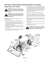
Outlet #1 (lower left) - connect the hydraulic line from the piston
ends of the bucket cylinders (roll back bucket).
Outlet #2 (upper left) - connect the hydraulic line from the cylinder
body ends of the bucket cylinders (dump bucket).
Outlet #3 (upper right) - connect the hydraulic line from the piston
ends of the boom cylinders (lower boom).
Outlet #4 (lower right) - connect the hydraulic line from the
cylinder body ends of the boom cylinders (raise boom).
Figure 8
• Check for ties that may be installed end to end around both of
the boom cylinders. Cut and remove the ties if present.
IMPORTANT: Re-start the tractor and perform the hydraulic test
described below in “Checking Implement Control Lever Opera-
tion” to assure that all implement control lever movements result
in the loader movements described. If loader movements do not
respond correctly, turn the tractor’s engine off, set the parking
brake and recheck all hydraulic connections as described above.
Loader control movements must be correct before proceeding.
IMPORTANT: If you were unable to connect the pistons of the
two bucket cylinders to the bucket rear mounting brackets as
instructed earlier, use the tractor’s implement control lever to
extend the pistons as needed and connect the cylinders now.
WARNING: Use extreme caution when perform-
ing the loader boom cylinder charging procedure.
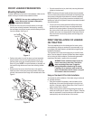
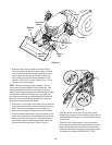
NOTE: For packaging purposes the two boom cylinders are
fully collapsed. This results in the loader masts being positioned
beyond their normal vertical position, which causes the loader’s
center of gravity to be shifted rearward of normal. Consequently
the loader hitch arms may not pivot downward when initially
extending the boom cylinders pistons. When performing the
initial priming of the boom cylinders, it will be necessary to apply
downward force on the front of the bucket (e.g.; placing weight on
bucket shave plate; an assistant applying downward pressure on
the bucket) to pivot the hitch arms downward and raise the loader
masts.
• While observing the hoses to ensure they do not become
pinched or stretched, slowly and carefully move the imple-
ment control lever rearward to extent the boom cylinders. The
loader hitch arms should pivot downward toward the ground
and raise the bottoms of the masts.
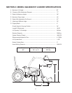
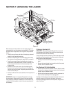
Base of Mast
LH Mount
Tubular Bar
Loader
Hitch Arms
2
1
3
4
Lower Boom
(#3-Blue)
Raise Boom
(#4-Green)
Dump Bucket
(#2-Yellow)
Curl Bucket
(#1-Red)
Hydraulic Outlets