


10
SECTION 8: INITIAL INSTALLATION
TRACTOR PREPARATION
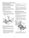
Remove the front weight bracket from the front of the tractor by re-
moving the six hex screws and nuts securing it to the front frame.
Store the front weight bracket for reinstallation when removing the
loader and attaching rear mounted equipment.
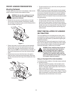
Installing the LH and RH Mounts
IMPORTANT: The LH and RH mounts are heavy and awkward
to handle. Usage of a lifting device (e.g. floor jack), or the aid of
an assistant, while positioning the tower mounts for installation is
recommended.
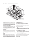
Install the RH and LH mounts as follows:
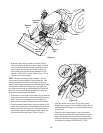
• Look at the RH mount (1) to note the configuration of the
holes on the mounting plate of the assembly.
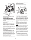
• From the right side of the tractor, locate the three holes in a
triangular pattern on the tractor’s clutch housing, and the two
vertical holes on the front frame. Remove the protective plugs
from the holes See Figure 3.
Figure 3
IMPORTANT: When positioning the RH mount on the tractor,
be especially careful to avoid damaging the small hydraulic lines
running along the bottom of the frame. Temporarily move the
rubber hose out of the way.
• Lift the RH mount (1) and carefully place against the tractor,
aligning its holes with the holes in the tractors clutch housing
and frame.
• Insert three hex cap screws (5) through the RH mount and
thread into the clutch housing. Insert two hex cap screws (6)
through the front of the mount and thread into the frame. In a
staggered pattern, evenly tighten the five hex cap screws to
secure the RH mount. Torque the screws to 145 - 167 ft. lbs.
(196-225 N•M). Refer to Figure 3.
Hex Cap
Screw
RH Mount
Clutch
Housing
Front
Frame
Hex Cap
Screw
• From the left side of the tractor, locate the mounting holes and
remove the protective plugs.
• Lift the LH mount (2) and carefully place against the tractor,
aligning its holes with the holes in the tractors clutch housing
and frame.
• Insert three hex cap screws (5) through the LH mount and
thread into the clutch housing. Insert two hex cap screws (6)
through the front of the mount and thread into the frame. In a
staggered pattern, evenly tighten all hex cap screws to secure
the LH mount. Torque the screws to 145 - 167 ft. lbs. (196-225
N•M). Refer to Figure 3.
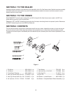
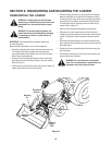
Installing the Front Mount Receiver
If not already done, remove the two lynch pins and withdraw the
mounting pins to separate the front mount receiver from the loader
hitch bracket (Refer to Figure 1).
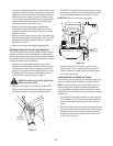
• Slide a flat washer (8) onto each of the eight hex cap screws
(7). Refer to Figure 4.
• Position the front mount receiver (3) so that its open channel
is facing downward. Then place the front mount receiver
against the front of the tractor frame (where the front weight
bracket was previously removed).
• Align the eight holes in the front mount receiver with the
corresponding holes in the front frame. While holding the
front mount receiver in position, insert eight hex cap screws
w/washers through the front mount receiver and tractor frame.
See Figure 4.
Figure 4
• Thread a hex lock nut (9) onto each hex cap screw. In a
staggered pattern, evenly tighten all hex cap screws and lock
nuts. Torque the fasteners to 60-70 ft. lbs. (81-94 N•M)
Hex Cap
Screw
Flat Washer
Hex Lock Nut
Front Mount
Receiver
Front
Frame