7 - EN
Appropriate installation
location
• Install your machine in environments
which have no risk of freezing and in a
stable and level position.
• Do not place your machine on a long
pile rug or on similar surfaces.
• Operate your machine in a well
ventilated, dust-free environment.
• Do not block the air ducts in front of
and under the machine with materials
such as long pile rugs or kitchen unit
plinths.
B Make sure that your machine is not
placed on the power cable.
B Keep at least 3 cm from the edges of
other furniture.
Under Counter Installation
• Leave at least 3 cm of space between
the side and rear walls of the machine
and the walls of the counter/cupboard
when installing your machine under a
counter or in a cupboard. Never use
the tumble dryer without top plate.
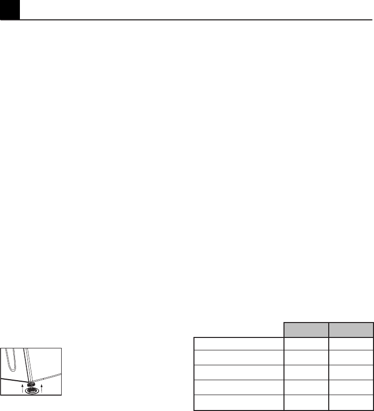
Adjusting the feet
In order to ensure that your machine
operates more silently and vibration-free,
it must stand level and balanced on its
feet. Front feet of your machine can
be adjusted. Balance the machine by
adjusting the feet.
1. Loosen the feet by hand.
2. Adjust them until the machine stands
level and firmly.
C Do not use any tools to loosen the
adjustable feet. Otherwise, they can be
damaged.
C Never unscrew the adjustable feet
from their housings.
2 plastic pieces supplied together with
the Operating Instructions prevent
your machine from slipping on wet and
slippery surfaces. To install these plastic
parts:
1. Tilt your machine to backwards.
2. Fit the plastic parts to the front
adjustable feet. Press on the plastic
parts to fix them in their places.
3. Check the balance of your machine
again and readjust the adjustable feet if
necessary.
Ventilation hose and
connection (for products
equipped with an outlet vent)
Ventilation hose assures exhausting of the
air from inside the machine.
Vented dryer has 1 air outlet.
Stainless sheet metal or aluminum pipes
can be used instead of the hose. The
diameter of the pipe to be used should
be minimum 10 cm.
Maximum hose and pipe lengths are
given in the table below.
Hose Pipe
Maximum length 4 m 5 m
1 elbow 45° -1.0 m -0.3 m
1 elbow 90° -1.8 m -0.6 m
1 elbow 90° short -2.7 m
1 wall passage -2.0 m -2.0 m
C Each elbow and other passages
should be subtracted from the above
maximum length.
To connect a ventilation hose;
1. Connect the air outlet hose to the
hose spacer piece by turning it anti-
clockwise.
2. Make the hose passages as shown
below.
3 Installation


