


113429-9 Telephone 01422 822282 19
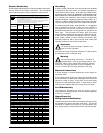
Electric Models Only
All electrically heated dryers must be connected to the electric
service shown on the dryer’s data label. The connecting
wires must be properly sized to handle the rated current.
Grounding
A ground (earth) connection must be provided and installed
in accordance with local, state, and national regulations or
codes of the country of origin. In the absence of these codes,
grounding must conform to applicable requirements of the
National Electrical Code ANSI/NFPA NO. 70-LATEST EDITION,
or in Canada, the installation must conform to applicable
Canada Standards: Canadian Electrical Codes Parts 1 & 2
CSA C22.1-1990 or LATEST EDITION. The ground connection
may be to a proven earth ground at the location service panel.
For added personal safety, when possible, it is suggested
that a separate ground wire (size per local codes) be
connected from the ground connection of the dryer to a
grounded cold water pipe. Do not ground to a gas pipe or hot
water pipe. The grounded cold water pipe must have
metal-to-metal connection all the way to the electrical ground.
If there are any nonmetallic interruptions, such as, a meter,
pump, plastic, rubber, or other insulating connectors, they
must be jumped out with a wire (size per local codes) and
securely clamped to bare metal at both ends.
Important
For personal safety and proper operation, the
dryer must be grounded.
Provisions are made for ground connection in each dryer at
the electrical service connection area.
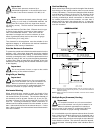
Warning
Electrical Grounding Instructions – This dryer is
equipped with a 3-prong (grounding) plug for your
protection against shock hazard and should be plugged
directly into a properly grounded 3-prong receptacle. Do
not cut or remove the grounding prong from this plug.
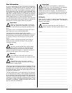
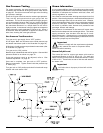
Electrical Connections
A wiring diagram is located behind the control panel for
connection data.
If local codes permit, power to the dryer can be made by the
use of a flexible UL listed power cord/pigtail (wire size must
conform to rating of dryer), or the dryer can be hard wired
directly to the service breaker panel. In both cases, a strain
relief must be installed where the wiring enters the dryer.
For CE Models Only
The means for disconnection from the supply must be
incorporated into wiring having a minimum contact separation
of 3.0mm in all poles.
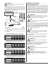
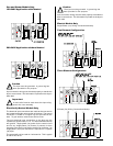
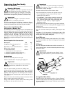
Single-Phase (1ø)
Wiring Connections/Hookup
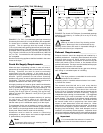
The electrical input connections are made into the rear service
box located at the upper right area of the dryer. The ground
connection is made to the copper lug, also provided in this
box. To gain access, the service box cover must be removed.
!
!
7/15/08
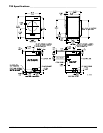
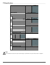
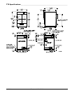
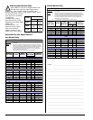
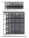
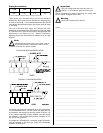
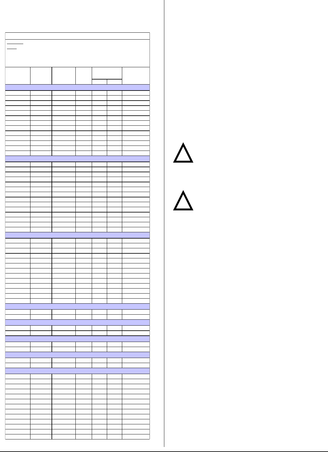
ELECTRICAL SERVICE SPECIFICATIONS
IMPORTANT:
NOTES
: A.
B.
C.
208 VAC AND 230/240 VAC ARE NOT THE SAME. When ordering, specify exact voltage.
When fuses are used they must be dual element, time delay, current limiting, class RK1 or RK5
ONLY. Calculate/determine correct fuse value, by applying either local and/or National Electrical
Codes to listed appliance amp draw data.
Circuit breakers are thermal-magnetic (industrial) type ONLY. For others, calculate/verify correct
breaker size according to appliance amp draw rating and type of breaker used.
Circuit breakers for 3-phase (3ø) dryers must be 3-pole type.
SERVICE
VOLTAGE
PHASE
WIRE
SERVICE
OVEN
kW
APPROX.
AMP DRAW
CIRCUIT
BREAKER
60 Hz 50 Hz
T20
200 1ø 2 5.6 32.7 32.7 45
208 1ø 2 4.1 24.2 — 35
208 1ø 2 6.1 34.0 — 45
220 1ø 2 6.8 35.6 — 45
230 1ø 2 5.0 — 26.4 35
230 1ø 2 7.4 — 36.8 50
240 1ø 2 5.4 27.1 — 35
240 1ø 2 8.1 38.4 38.4 50
208 3ø 3 6.5 22.7 — 30
240 3ø 3 7.5 22.6 — 30
380 3ø 4 6.8 — 15.0 20
400 3ø 4 7.5 — 15.5 20
416 3ø 4 8.1 — 15.8 20
T30
200 1ø 2 12.5 68.4 67.7 90
208 1ø 2 7.9 43.8 — 60
208 1ø 2 13.5 70.7 — 90
230 1ø 2 8.3 — 41.3 60
230 1ø 2 12.4 — 59.1 80
240 1ø 2 9.0 42.7 — 60
240 1ø 2 13.5 61.5 — 80
208 3ø 3 13.5 43.3 — 60
220 3ø 3 11.3 35.3 — 50
230 3ø 3 12.4 — 36.5 50
240 3ø 3 13.5 37.7 — 50
380 3ø 4 11.3 22.8 22.6 40
400 3ø 4 12.4 — 23.1 40
416 3ø 4 13.5 — 23.7 40
T50
200 1ø 2 14.8 82.1 — 110
208 1ø 2 16.0 85.1 — 110
220 1ø 2 13.4 68.8 69.4 90
230 1ø 2 14.7 — 72.3 100
240 1ø 2 16.0 74.2 75.1 100
200 3ø 3 14.8 — 51.0 70
208 3ø 3 16.0 52.6 — 70
220 3ø 3 13.4 43.0 43.6 60
230 3ø 3 14.7 — 45.3 60
240 3ø 3 16.0 46.0 — 60
380 3ø 4 13.4 28.0 28.6 40
400 3ø 4 14.8 — 29.8 40
416 3ø 4 16.0 — 30.7 40
T50 Dual Voltage 480 / 120
120 1ø 2 0.0 13.2 — 15
480 3ø 3 16.0 19.2 — 25
T50 Dual Voltage 480 / 240
240 1ø 2 0.0 6.5 — 15
480 3ø 3 16.0 19.2 — 25
T50 Dual Voltage 600 / 120
120 1ø 2 0.0 13.2 — 15
600 3ø 3 16.0 15.4 — 20
T50 Dual Voltage 600 / 240
240 1ø 2 0.0 6.5 — 15
600 3ø 3 16.0 15.4 — 20
T75
200 1ø 2 20.3 109.8 — 150
208 1ø 2 22.0 113.9 — 150
220 1ø 2 18.5 91.7 92.3 125
230 1ø 2 20.3 — 96.3 125
240 1ø 2 22.0 99.2 — 125
208 3ø 3 22.0 69.2 — 90
220 3ø 3 18.5 56.2 56.8 80
230 3ø 3 20.3 — 59.1 80
240 3ø 3 22.0 60.4 — 80
380 3ø 4 18.5 35.6 — 45
380 3ø 4 18.5 — 36.2 50
400 3ø 4 20.3 — 37.8 50
416 3ø 4 22.0 — 39.1 50