


18 JLA Limited 113429-9
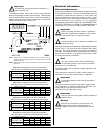
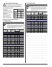
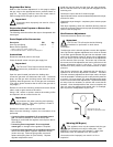
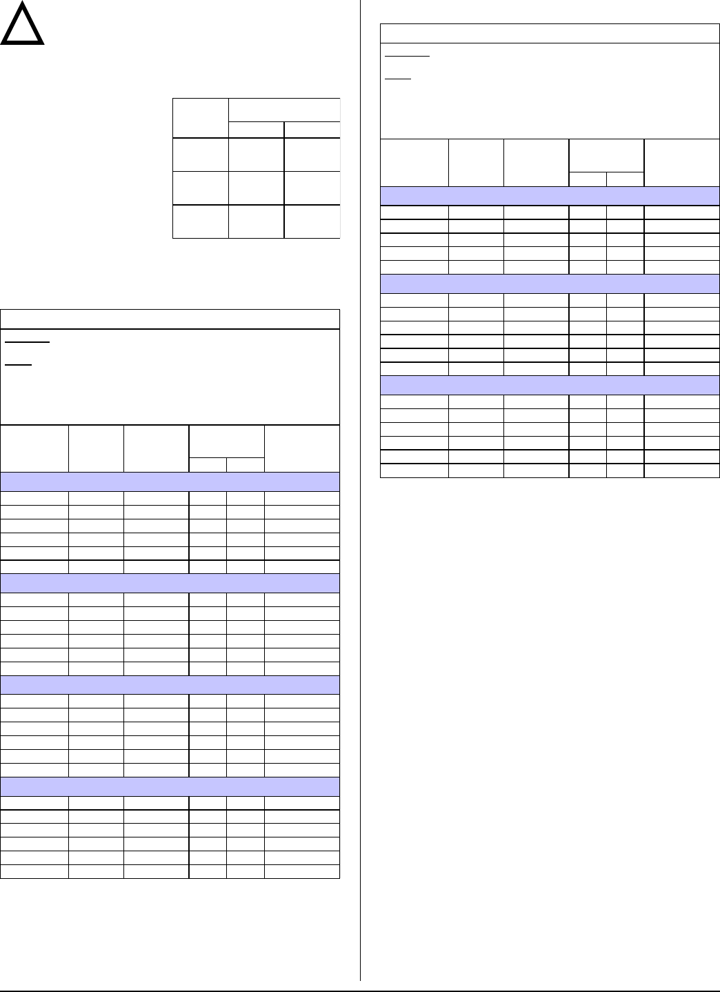
Warning (Gas Models Only)
Dryers built for use with a voltage between 200
and 240 must verify the input voltage during
installation. If the nominal voltage is outside of the
medium tolerances shown on the diagram below, adjust
!
TERM
LINE VOLTAGE
50 Hz 60 Hz
HIGH
260
226
283
249
MED
239
208
260
230
LOW
217
189
236
208
NOTES ______________________________________________________
_____________________________________________________________
_____________________________________________________________
_____________________________________________________________
_____________________________________________________________
_____________________________________________________________
_____________________________________________________________
_____________________________________________________________
_____________________________________________________________
_____________________________________________________________
_____________________________________________________________
_____________________________________________________________
_____________________________________________________________
_____________________________________________________________
_____________________________________________________________
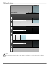
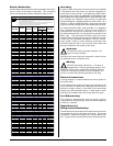
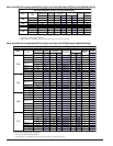
ELECTRICAL SERVICE SPECIFICATIONS
IMPORTANT:
NOTES
: A.
B.
C.
208 VAC AND 230/240 VAC ARE NOT THE SAME. When ordering, specify
exact voltage.
When fuses are used they must be dual element, time delay, current limiting,
class RK1 or RK5 ONLY. Calculate/determine correct fuse value, by applying
either local and/or National Electrical Codes to listed appliance amp draw data.
Circuit breakers are thermal-magnetic (industrial) motor curve type ONLY.
For others, calculate/verify correct breaker size according to appliance amp
draw rating and type of breaker used.
Circuit breakers for 3-phase (3ø) dryers must be 3-pole type.
SERVICE
VOLTAGE
PHASE
WIRE
SERVICE
APPROX.
AMP DRAW
CIRCUIT
BREAKER
60 Hz 50 Hz
T20
120 1ø 2 8.9 — 15
200 1ø 2 7.7 7.8 15
208 1ø 2 7.6 — 15
220 1ø 2 — 7.4 15
230 1ø 2 — 7.3 15
240 1ø 2 7.2 7.0 15
T30
120 1ø 2 10.3 — 15
200 1ø 2 8.7 8.8 15
208 1ø 2 8.4 — 15
220 1ø 2 8.1 8.1 15
230 1ø 2 — 7.4 15
240 1ø 2 7.7 7.0 15
T50
120 1ø 2 15.6 — 20
200 1ø 2 10.5 — 20
208 1ø 2 10.5 — 20
220 1ø 2 10.0 10.7 20
230 1ø 2 — 10.8 20
240 1ø 2 9.7 — 20
T75
120 1ø 2 15.6 — 20
200 1ø 2 10.5 — 20
208 1ø 2 10.5 — 20
220 1ø 2 10.0 10.7 20
230 1ø 2 — 10.8 20
240 1ø 2 9.7 — 20
Steam Models Only
7/15/08
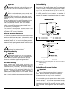
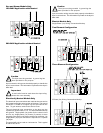
the autotransformer, located
near the burner assembly.
To adjust the
autotransformer wiring,
place the red wire on the
appropriate tap (HIGH, MED,
LOW) of the
autotransformer. For
additional wiring details,
refer to the electrical
diagram located on the
inside of the control panel.
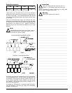
Electrical Service Specifications
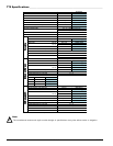
Gas Models Only
7/15/08
ELECTRICAL SERVICE SPECIFICATIONS
IMPORTANT:
NOTES
: A.
B.
C.
208 VAC AND 230/240 VAC ARE NOT THE SAME. When ordering, specify
exact voltage.
When fuses are used they must be dual element, time delay, current limiting,
class RK1 or RK5 ONLY. Calculate/determine correct fuse value, by applying
either local and/or National Electrical Codes to listed appliance amp draw data.
Circuit breakers are thermal-magnetic (industrial) motor curve type ONLY.
For others, calculate/verify correct breaker size according to appliance amp
draw rating and type of breaker used.
Circuit breakers for 3-phase (3ø) dryers must be 3-pole type.
SERVICE
VOLTAGE
PHASE
WIRE
SERVICE
APPROX.
AMP DRAW
CIRCUIT
BREAKER
60 Hz 50 Hz
T30
120 1ø 2 9.3 — 15
208 1ø 2 6.2 6.0 15
220 1ø 2 5.6 5.5 15
230 1ø 2 — 5.4 15
240 1ø 2 5.1 — 15
T50
120 1ø 2 14.4 — 20
200 1ø 2 8.2 — 20
208 1ø 2 8.2 — 20
220 1ø 2 7.8 8.4 20
230 1ø 2 — 8.5 20
240 1ø 2 7.6 — 20
T75
120 1ø 2 14.4 — 20
200 1ø 2 8.2 — 20
208 1ø 2 8.2 — 20
220 1ø 2 7.8 8.4 20
230 1ø 2 — 8.5 20
240 1ø 2 7.6 — 20