


113401-18 www.amdry.com 23
!
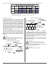
Warning (CE Dryers)
This appliance must only be
operated with the gas type
indicated on the dryer’s data plate. If the
appliance is converted (gas type changed),
a data plate amendment must be obtained
from American Dryer Corporation.
Conversions done improperly can result in
a fire or explosion!
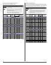
Gas Pressure Testing ______
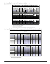
For proper operation, the gas pressure must
be correct, consistent and maintained at the
gas pressure rates shown on page 19.
Provisions are made at the gas valve for
taking gas pressure readings.
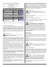
There are two types of devices used to
measure gas pressure. They are the spring/
mechanical type gauge and the manometer.
The use of the spring/mechanical type gauge
is not recommended because they are very
easily damaged and are not always accurate.
The preferred type of gauge is the manometer
because it is a simple device to use and is
highly accurate. A manometer is simply a
glass or transparent plastic tube with a scale
graduated in inches or millibars. When it is
filled with water and pressure is applied, the
water in the tube rises, showing the exact
gas pressure.
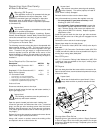
Gas Pressure Test Procedure
Turn gas cock in gas supply line to “OFF”
position.
50 Hz dryers: Back out miniature screw inside
pressure tap and attach manometer (refer to
the illustration on page 21).
60 Hz dryers: Install pressure tap and attach
manometer (refer to the illustration on page
21).
Turn gas cock to “ON” position.
Start the dryer in Heat Mode and wait for
ignition. Gas manifold pressure should be
as shown on page 19.
If the gas pressure needs to be adjusted, refer to “Gas Pressure Adjustment”
on page 22.
Once test is complete, turn gas cock to “OFF” position. Remove manometer.
Tighten screw inside the pressure tap or install plug.
Turn gas cock to “ON” position and check for leaks with soap solution with
main burner “ON.”
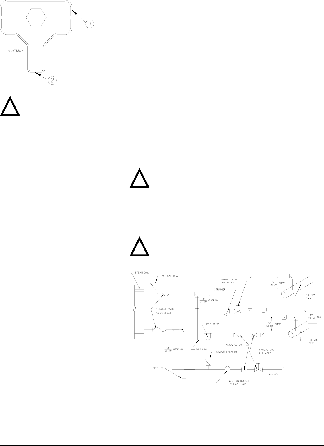
Steam Information _______________________________
It is your responsibility to have all plumbing connections made by a qualified
professional to ensure that the steam plumbing installation is adequate and
conforms with local, state, and country regulations or codes.
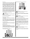
Care must be exercised when leveling steam dryers into final position. After
leveling the dryer, check the downward pitch of the heat exchanger from front
to rear with a level. Likewise, check the downward pitch of the return
condensate manifold toward its outlet part. Absence of these downward
pitches will result in probable water hammer and premature heat exchanger
fracture and leakage.
The presence of condensate in the steam will cause water hammer and
subsequent heat exchanger failure. The steam supply connection must be
taken from the top of a well-dripped steam main. If the supply run-out to the
dryer exceeds 25 feet (7.6 meters), it should be dripped just before the control
valve with a proper trap and dirt pocket.
Important
Failure to comply with the requirements stipulated in this manual
can result in component failure, which will void the warranty.
Steam Coil pH Level
The normal pH level for copper type steam coils must be maintained between
a value of 8.5 to 9.5. For steel type steam coils the pH level must be maintained
between a value of 9.5 to 10.5. These limits are set to limit the acid attack of
the steam coils.
Important
Coil failure due to improper pH level will void the warranty.
!
!
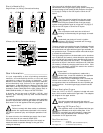
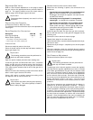
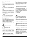
Edge #1 for vent cap
Edge #2 for adjustment screw