


20 American Dryer Corp. 113401-18
Piping/Connections
The dryer is provided with two 1/2” N.P.T. (3/8” B.S.P.T. for CE
and Australian dryers) inlet pipe connections (1 for each
tumbler) at the rear of the dryer. If a separate feed is provided
for each tumbler from the main supply line (header), then a
1/2” (12.7 mm) line connection is sufficient. However, if the
top and bottom tumbler connections are connected together,
the supply from the header must be increased to 3/4-inch
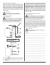
(19.05 mm). There should be a minimum 6-inch (15.24 cm)
clearance between the back guard and the first bend in the
gas piping for ease of servicing. It is recommended that a
gas shutoff valve be provided to the gas supply line of each
dryer for ease in servicing.
The size of the main gas supply line (header) will vary
depending on the distance this line travels from the gas meter
or, in the case of L.P. gas, the supply tank, other gas-operated
appliances on the same line, etc. Specific information
regarding supply line size should be determined by the gas
supplier.
Note
Undersized gas supply piping can create a low or
inconsistent pressure, which will result in erratic
operation of the burner ignition system.
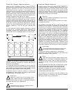
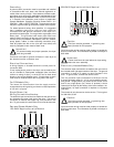
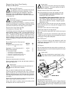
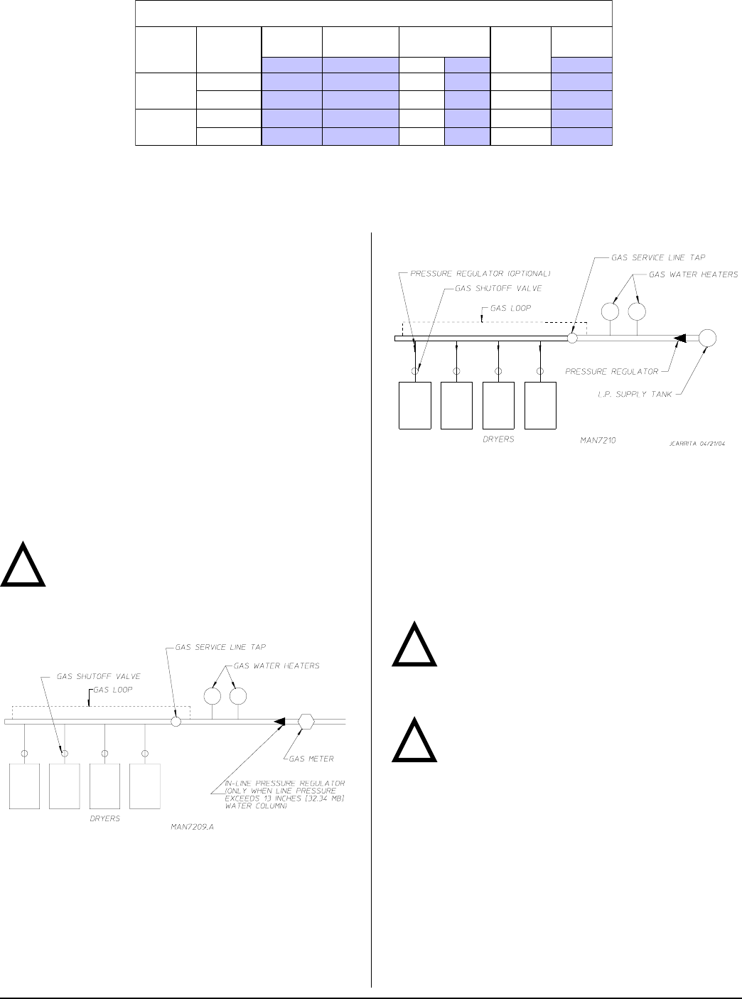
TYPICAL NATURAL GAS INSTALLATION
!
Consistent gas pressure is essential at all gas connections.
It is recommended that a 3/4-inch (19.05 mm) pipe gas loop
be installed in the supply line servicing a bank of dryers. An
in-line pressure regulator must be installed in the gas supply
line (header) if the (natural) gas pressure exceeds 13.0 in
WC (32.34 mb) pressure.
A plugged tap, accessible for a pressure gauge connection,
must be installed in the main gas supply line immediately
upstream of the dryers.
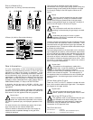
Important
Pipe joint compounds that resist the action of
natural, L.P., and butane gases must be used.
Test all connections for leaks by brushing on a soapy water
solution (liquid detergent works well).
Warning
Never test for leaks with a flame!!!
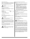
TYPICAL L.P. GAS INSTALLATION
!
!
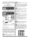
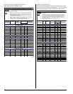
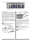
Heat Input/Gas Consumption/Orifice (Injector) Data (For AGA [Australian] Models Only)**
Shaded areas are stated in metric equivalents
* Information is per pocket/tumbler.
** Consult factory for elevations over 2,000 feet (610 meters) for correct orifice size.
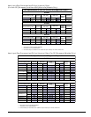
Gas Specifications for AGA Approved Dryers
Model
Gas
Type
Supply
Pressure
*Gross
Heat Input
Orifice Size
*Orifice
(Injector)
Quantity
Burner
Pressure
kPa MJ/h DMS mm kPa
SL2020
Natural
1.7-3.2 42.20
30
3.264
1
0.67
Propane
2.75 42.20
49
1.854
1
2.30
SL3131
Natural
1.7-3.2 58.03
22
3.988
1
0.69
Propane
2.75 58.03
44
2.184
1
2.49