


14 American Dryer Corp. 113344-9
IMPORTANT: For extended ductwork runs, the cross section area of the ductwork can only be
increased to an extent. When the ductwork approaches the maximum limits noted in
this manual, a professional heating, ventilating, and air-conditioning (HVAC) firm
should be consulted for proper venting information.
ALL ductwork should be smooth inside with no projections from sheet metal screws or other obstructions,
which will collect lint. When adding ducts, the duct to be added should overlap the duct to which it is to be
connected.
ALL ductwork joints must be taped to prevent moisture and lint from escaping into the
building. Inspection doors should be installed at strategic points in the exhaust ductwork for periodic
inspection and cleaning of lint from the ductwork.
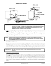
NOTE: When the exhaust ductwork passes through a wall, ceiling, or roof made of combustible
materials, the opening must be 2-inches (5.08 cm) larger than the duct (all the way around).
The duct must be centered within this opening.
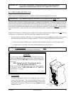
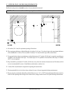
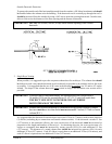
Outside Ductwork Protection
To protect the outside end of the horizontal ductwork from the weather, a 90° elbow bent downward
should be installed where the exhaust exits the building. If the ductwork travels vertically up through the
roof, it should be protected from the weather by using a 180º turn to point the opening downward. In
either case, allow at least twice the diameter of the duct between the duct opening and the nearest obstruction.
IMPORTANT: DO NOT use screens, louvers, or caps on the outside opening of the exhaust
ductwork.
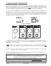
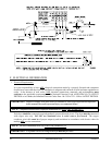
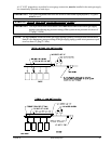
3. Multiple Dryer (Common) Venting
If it
is not feasible to provide separate exhaust ducts for each dryer, ducts from individual dryers may be
channeled into a “common main duct.” The individual ducts should enter the bottom or side of the main
duct at an angle not more than 45º in the direction of airflow and should be spaced at least 38-1/4”
(97.15 cm) apart. The main duct should be tapered, with the diameter increasing before each individual
duct (14-inch [35.56 cm] minimum for gas models and 16-inch [40.64 cm] minimum for steam models) is
added.