


21
3. Electrical Connections
NOTE: A wire diagram is located in the front electrical control box for connection data.
a. GAS MODELS and STEAM MODELS ONLY
NOTE: A CIRCUIT SERVING EACH DRYER MUST BE PROVIDED.
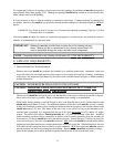
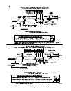
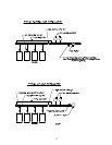
1) Single-phase (1ø) Wiring Connections (Hookup)
The electrical connections on ALL single-phase (1ø) gas models and steam model dryers are made
into the rear service box located at the upper left area of the dryer.
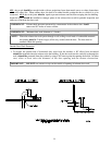
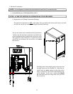
For gas and steam dryers manufactured for operation at
3 phase (3ø), the electrical connections are made at the
power distribution block located in the service box at the
rear, upper left corner of the dryer. To gain access to the
service box and contactor, the service box cover must
be removed.
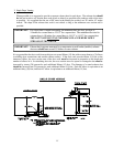
Providing local codes permit, power to the dryer can
be made by the use of a flexible U.L. listed cord or
pigtail (wire size must conform to the rating of the
dryer), or the dryer can be hard wired directly to the
service breaker. In all cases, a strain relief should
be used both where the wiring enters the dryer and
the service box.