


113247-3 www.amdry.com 27
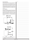
The opposite side of each linkage will then be fastened to
the appropriate damper assembly. There are 5 holes on
each damper flange. The best adjustment is usually found
in the center hole. However, this may not hold true on every
damper assembly due to manufacturing tolerances. The
linkage is then fastened to the damper flange in the same
manner as step 2. Refer to figure 1. The linkage support
assembly should be turned CCW until the damper
assemblies seat securely against the steam coils and the
setscrew is to be tightened securely.
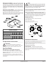
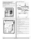
The lever arm assembly should then be positioned on the
center bar on the front of the steam damper assembly. With
the damper assemblies seating securely against the steam
coils, the lever arm should be positioned between 8:00 and
9:00. These connections are all shown in figure 2.
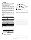
Once the connections are all made, turn the activating bracket
assembly CW. The entire assembly should turn freely without
binding or excessive force. The bottom of the damper
assemblies should both meet approximately in the center of
the plenum. The damper assemblies should meet almost
flush. Refer to figure 3. If the dampers resist closing or if they
do not meet almost flush, it may be necessary to move either
one or both of the linkages up or down on the damper flange
depending on the adjustment required.
Once proper adjustment has been accomplished, power up
the dryer and activate a cycle. Observe the closing of the
damper assembly. Again the dampers must meet. If they do
not it may be necessary to readjust again. The misalignment
may also be due to loose setscrews. If proper adjustment
cannot be obtained, contact the technical support department
at ADC for assistance.
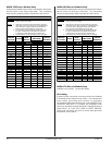
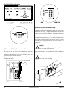
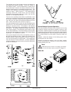
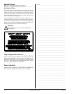
Steam Damper System Operation
The steam damper, as shown below, allows the coil to stay
constantly charged eliminating repeated expansion and
contraction. When the damper is opened, the air immediately
passes through the already hot coil, providing instant heat to
start the drying process. When the damper is closed, ambient
air is drawn directly into the tumbler, allowing a rapid cool
down.
Diagram 1 shows the damper in the heating (open) mode,
allowing heat into the tumbler.
Diagram 2 shows the damper in the cool down (closed)
mode, pulling ambient air directly into the tumbler without
passing through the coils.
Note
With the dryer off or with no air supply, the damper
is in the cool down mode as shown in Diagram 2.
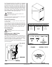
ADH-120
!