


26 American Dryer Corp. 113247-3
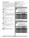
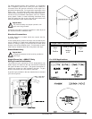
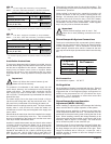
Compressed
Air Supply
Air Pressure
Normal 80 psi
5.51 bar
Minimum Supply 70 psi
4.82 bar
Maximum Supply 90 psi
6.21 bar
!
!
The supply line and the return line should be insulated. This
will save energy and provide for the safety of the operator and
maintenance personnel.
Water pockets in the supply line, caused by low points, will
provide wet steam to the coil possibly causing steam coil
damage. All horizontal runs of steam supply piping should
be pitched 1/4-inch (6.35 mm) for every 1 foot (0.31 meters)
back towards the steam supply header causing the
condensate in the line to drain to the header. Install a bypass
trap in any low point to eliminate wet steam.
Important
Flexible hoses/couplings must be used. Coil
failure due to hard plumbing connections will void
the warranty.
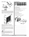
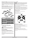
Steam Damper Air System Connections
The dryer is manufactured with a pneumatic (piston) damper
system and door interlock which requires an external supply
of clean compressed air. The air connection is made to the
steam damper solenoid valve which is located at the rear
inner top area of the dryer just above the electric service relay
box.
Air Requirements
Shaded areas are stated in metric equivalents
Air Connection
Air connection to system – 1/8” N.P.T.
Air Regulation
No air regulator or filtration is provided with the dryer. External
regulation/filtration of 80 psi (5.51 bar) must be provided. It is
suggested that a filter/regulator/gauge arrangement be
added to the compressed air line just before the dryer
connection. This is necessary to ensure that correct and
clean air pressure is achieved.
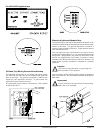
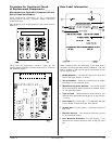
Steam Damper System Operation
Adjustment (ADSH-120 Only)
When installing or adjusting the steam damper the following
steps must be taken for proper operation of the system.
The linkage support assembly is placed on the center bar
inside the plenum between the coils. The assembly must be
positioned such that the locking collar is facing the rear of the
dryer. When installing, examine the linkage assembly to be
certain that collar has been welded on the proper side of the
assembly. Refer to figure 1 on next page. The collar should
not be locked into place on the center bar yet.
Facing the front of the coil assembly, the small linkage arm
will be fastened to the left side of the linkage assembly and
the large linkage arm will be positioned to the right. Each
linkage is fastened with a clevis pin, a cotter pin, and a
sufficient number of washers to allow the linkage to swivel
without sloppiness.
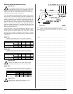
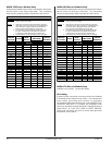
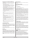
OPERATING STEAM PRESSURE
Maximum 125 psig*
861.84 kPa
Heat Input (Normal Load) 13
Bhp
Consumption (Approximate)
@ 125 psi (8.6 bar)
450 lb/hr
200.2 kg/hr
OPERATING STEAM PRESSURE
Maximum 125 psig*
861.84 kPa
Heat Input (Normal Load) 19
Bhp
Consumption (Approximate)
@ 125 psi (8.6 bar)
725 lb/hr
329.1 kg/hr
ADH-120
Inlet -------1” N.P.T. supply line connection (1 at top manifold).
Return ---1/2” N.P.T. return line connection (1 at bottom manifold).
Shaded areas are stated in metric equivalents
* The minimum operating pressure for optimum results is 100 psig (689.47
kPa).
ADH-170
Inlet -------1-1/2” N.P.T. supply line connection (1 at top manifold).
Return ---1-1/2” N.P.T. return line connection (1 at bottom manifold).
Shaded areas are stated in metric equivalents
* The minimum operating pressure for optimum results is 100 psig (689.47
kPa).
Installation Instructions
To ensure an adequate supply of steam is provided, be sure
that the steam supply lines and steam return lines are sized
and laid out as stipulated in this manual. Inadequate steam
supply lines and steam return lines or improper steam
plumbing will result in poor performance and can cause
component failure. Clean, dry steam must be provided to the
dryer.
Impor tant
Steam coil failure due to water hammer by wet
steam will void the warranty.
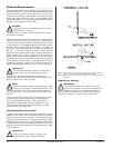
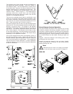
The presence of condensate in the steam supply line will
cause water hammer and subsequent heat exchanger
(steam coil) failure. The steam supply connection into the
main supply line must be made with a minimum 10-inch
(25.4 cm) riser. This will prevent any condensate from draining
towards the dryer.
The steam supply line to the dryer must include a 12-inch
(30.48 cm) riser along with a drip trap and check valve. This
will prevent any condensate from entering the steam coil.
Flexible hoses or couplings must be used. The dryer vibrates
slightly when it runs and this will cause the steam coil
connections to crack if they are hard piped to the supply and
return mains.
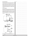
Shutoff valves for each dryer should be installed in the supply
line, return line, and drip trap return line. This will allow the
dryer to be isolated from the supply main and the return main
if the dryer needs maintenance work.
Install an inverted bucket steam trap and check valve at least
12-inches (30.48 cm) below the steam coil as close to the
coil as possible. A trap with a minimum capacity of 500 lb
(226.79 kg) of condensate per hour at 125 psi (8.62 bar) is
needed for each ADH-75 unit; 1,000 lb (453.59 kg) for each
ADH-120 unit; and 1,500 lb (680.38 kg) for each ADH-170
unit. (Based on 2 times the steam consumption per hour.)