


15
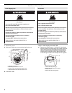
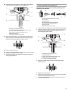
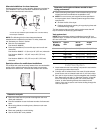
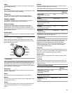
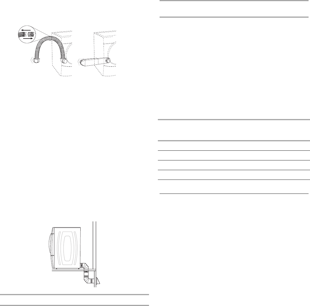
Alternate installations for close clearances
Venting systems come in many varieties. Select the type best for
your installation. Two close-clearance installations are shown.
Refer to the manufacturer’s instructions.
A B
A.Over-the-top installation (also available with one offset elbow)
B.Periscope installation
NOTE: The following kits for close clearance alternate
installations are available for purchase. To order, please see
the “Assistance or Service” section.
■ Over-the-Top Installation:
Part Number 4396028
■ Periscope Installation (For use with dryer vent to wall vent
mismatch):
Part Number 4396037 - 0" (0 mm) to 18" (457 mm) mismatch
Part Number 4396011 - 18" (457 mm) to 29" (737 mm)
mism
atch
Part Number 4396014 - 29" (737 mm) to 50" (1270 mm)
mismatch
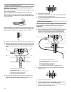
Special provisions for mobile home installations
The exhaust vent must be securely fastened to a noncombustible
portion of the mobile home structure and must not terminate
beneath the mobile home. Terminate the exhaust vent outside.
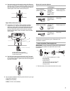
Determine vent path
■ Select the route that will provide the straightest and most
direct path outdoors.
■ Plan the installation to use the fewest number of elbows and
turns.
■ When using elbows or making turns, allow as much room
as possible.
■ Bend vent gradually to avoid kinking.
■ Use the fewest 90° turns possible.
Determine vent length and elbows needed for best
drying performance
■ Use the following Vent system chart to determine type of vent
material and hood combinations acceptable to use.
■ NOTE: Do not use vent runs longer than those specified in
the Vent system chart. Exhaust systems longer than those
specified will:
■ Shorten the life of the dryer.
■ Reduce performance, resulting in longer drying times and
increased energy usage.
The Vent system chart provides venting r
equirements that will
help to achieve the best drying performance.
Vent system chart
NOTE: Side and bottom exhaust installations have a 90º turn
inside the dryer. To determine maximum exhaust length, add one
90º turn to the chart.
Number of
90º turns
or elbows
Type of
vent
Box or
Louvered
hoods
Angled
hoods
0 Rigid metal 64 ft (20 m) 58 ft (17.7 m)
1 Rigid metal 54 ft (16.5 m) 48 ft (14.6 m)
2 Rigid metal 44 ft (13.4 m) 38 ft (11.6 m)
3 Rigid metal 35 ft (10.7 m) 29 ft (8.8 m)
4 Rigid metal 27 ft (8.2 m) 21 ft (6.4 m)
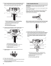
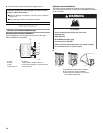
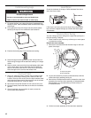
Install Vent System
1. Install exhaust hood. Use caulking compound to seal exterior
wall opening around exhaust hood.
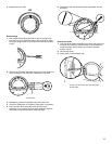
2. Conn
ect vent to exhaust hood. Vent must fit inside exhaust
hood. Secure vent to exhaust hood with 4" (102 mm) clamp.
3. Run ve
nt to dryer location. Use the straightest path possible.
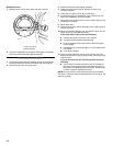
See “Determine vent path” in “Plan Vent System.” Avoid 90º
turns. Use clamps to seal all joints. Do not use duct tape,
screws, or other fastening devices that extend into the
interior of the vent to secure vent. Items sticking through the
vent can catch lint.