


Installation
801504
22
© Copyright, Alliance Laundry Systems LLC – DO NOT COPY or TRANSMIT
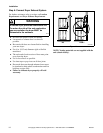
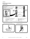
Electrical Plug Connection
Three-Wire Plug
Figure 26
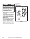
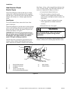
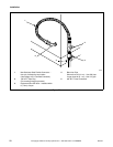
1. Remove access cover from rear of dryer.
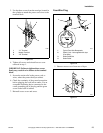
Figure 27
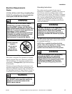
2. Use a strain relief and insert end of power cord
through power supply hole.
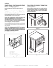
Figure 28
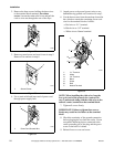
D816I
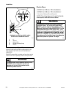
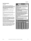
1 3-Wire Grounded Neutral 120/240 Volt, 60 Hertz
AC 1 Phase Service Entrance Switch Box
(See NOTE above)
4 Metallic or Non-Metallic Sheathed Cable
(Copper wire only)
5 Pigtail to Dryer (See NOTE above)
2 30 Ampere Fuses or Circuit Breaker 6 Neutral
3Neutral Wire 7 Terminal Block in Dryer
NOTE: The power cord (pigtail) is NOT supplied with the electric
dryer. Type of pigtail and gauge of wire must conform to local
codes and instructions.
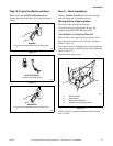
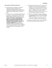
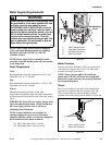
The method of wiring the dryer is optional and subject to local
code requirements.
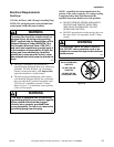
NOTE: Connect the dryer to the power supply with the
MAXIMUM RATED VOLTAGE listed on the nameplate.
1
2
3
4
5
6
7
POWER SUPPLY POWER SUPPLY
INTERMEDIATE
FUSE BOX (May
be omitted if
service entrance
box is fused)
WALL RECEPTACLE
PIGTAIL CONNECTION
L1 L2 L1 L2
DIRECT CONNECTION
INTERMEDIAT
E
SHUT-OFF BO
X
(May or may
not be fused)
120 ± 12
V.A.C.
A typical
30-Amp
Three-wire
Receptacle
NEMA Type
10-30R
120 ± 12
V.A.C.
240 ± 12
V.A.C.
NOTE: Use COPPER WIRE only. ’
Shorter than 15
(4.5 m) use 10 A.W.G.
Longer than 15
(4.5 m) use 8 A.W.G.
D695I
D696I