


Installation
F232158
16
© Copyright, Alliance Laundry Systems LLC – DO NOT COPY or TRANSMIT
Electrical Installation
Input Voltage Requirements
If input voltage measures above 240 Volt for a
200 Volt drive or above 440 Volt for a 400 Volt
drive, ask the power company to lower voltage.
For voltages above or below listed specifications,
contact Customer Service or a distributor for buck/
boost transformer recommendation.
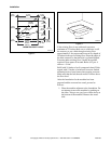
If machine is intended for four-wire service, a neutral
leg must be provided by power company.
If a delta supply system is used on a four-wire model,
connect high leg to L3.
IMPORTANT: Improper connections will result in
equipment damage and will void warranty.
Connection Specifications
IMPORTANT: Connection must be made by a
qualified electrician using wiring diagram provided
with machine, or according to accepted European
standards for CE-approved equipment.
Connect machine to an individual branch circuit not
shared with lighting or other equipment. Shield
connection in a liquid-tight or approved flexible
conduit. Proper conductors of correct size must be
installed in accordance with National Electric Code or
other applicable codes.
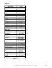
Use wire sizes indicated in the Electrical Specifications
chart for runs up to 50 feet (15 m). Use next larger size
for runs of 50 to 100 feet (15 to 30 m). Use two sizes
larger for runs greater than 100 feet (30 m).
The UW50 is provided with a thermal overload
protector in the drive motor windings and a separate
fuse for the control circuit. However, a separate three-
phase circuit breaker must be installed for protection
against shorts. DO NOT USE FUSES.
For proper over current protection, the circuit breaker
should be a 30 Amp capacity unit rated for
208-240 Volts and should be a three-phase breaker so
that in the event that one leg should be removed from
the machine, all three legs will be disconnected to
prevent damage to the motor.
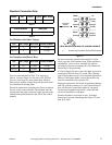
The wire for the service connection should be a
minimum size of 8 gauge (AWG) for 208-240 Volt
installations. Refer to Table 7.
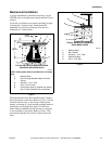
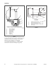
The connections should be made by a qualified
electrician and in accordance with the wiring diagram
provided with the machine.
When the machine is started, check that the cylinder
rotates in the correct direction during the spin (extract)
step, i.e., clockwise as seen from the front of the machine.
If the machine rotates in the wrong direction, two of
the lines are to be interchanged at the power connection
terminal (reverse L1 and L2 – do not reverse L3).
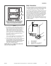
Hazardous Voltage. Can cause shock,
burn or cause death. Allow machine
power to remain off for two minutes prior
to working in and around AC inverter
drive.
W359
WARNING
Hazardous Voltage. Can cause shock,
burn or death. Verify that a ground wire
from a proven earth ground is connected
to the lug near the input power block on
this machine.
W360
WARNING
Turn off power and water before
attempting any maintenance, repairs, or
service, or before opening any service
panel or door. This machine must be
connected and grounded in accordance
with the National Electric Code and/or any
other applicable code.
W448
WARNING