


© Copyright, Alliance Laundry Systems LLC – DO NOT COPY or TRANSMIT
Operation
11
F232161
Test Procedure
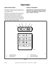
1. The WE-4 and WE-5 Programmable Computer,
with its display/fuse board should be easier to
maintain than other type controls. The following
procedure should help to eliminate problems and
determine if components are defective.
2. Test equipment required:
a. 20K OHM/Volt AC-DC voltmeter
b. Programmable computer diagram, WE-4
page 43, WE-5 page 44.
c. Display board diagram, drawing #2091
3. Power Up
a. When AC power is turned on, after
30 seconds the computer should read
“NEXT”.
b. Door unlock solenoid should work if Door
Unlock button is depressed.
c. If these are correct, go to step 5.
4. If computer does not read “NEXT” or does not
light:
a. Examine display board; the door light (DR)
should be on and all others off.
b. If not, check 2 AMP fuse on side of module.
c. Check for 115 volts AC between AC HOT
(ACH) and AC NEUTRAL (ACN) at top
center of display board. (Ref. Drawing #2091)
d. Be certain that all plugs are correctly installed
on the computer board.
e. If all above check OK, remove the 6 pin plug
(J-1) just above the transformer on the
computer board. Carefully check for 115 volt
AC between pins 1 and 6; if correct voltage is
there, replace computer board.
5. If computer reads “NEXT”:
a. Test the keypad, first with the keyed mode
switch in the Run position. A beep tone
should sound as each key is pressed.
NOTE: Keys should be pressed at their centers and
only hard enough to activate them. With the
computer showing “NEXT”, press each of the
15 keys not including the START key and listen for
each beep. After pressing all 15 keys (except
START), press 0 twice then press the START key.
Display should read “NOGO00”.
b. When the DISPLAY TEMP. key is pressed,
the computer display should change to show
the temperature inside the sump. When key is
released, the display should return to previous
read-out.
c. Turn the keyed mode switch to Program and
press “Display/Cycle”. Read-out should show
“CY--”. Then press 0 twice.
d. Press the CLEAR/STOP key. Display should
return to “NEXT”.
e. Return Mode switch to the Run position.
6. If keypad does not function as above:
a. Check the plug at the bottom center of
computer board for proper installation. (P-1)
b. If the plug is correct, proceed to “Replacing
Keypad” section.
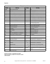
7. Test Cycle
a. Cycle 01 is a preprogrammed test cycle. If it
has not been erased, it may be used to check
all functions of the machine.
b. Start this cycle by pressing 0, then 1, then the
START key.
c. Display should show “CL01” with two dots
indicating water valves turned on. (Refer to
Table 1.)
d. On the display/fuse board inside the control
module, these lights should be lit: Cold Fill
(CF), Cold Spray (CS), Drain (DN), plus
Forward (FW) and Reverse (RV) should
alternate on and off. (Ref. Drawing No. 2091)
e. Printed program will indicate which lights to
expect for each step. (Ref. Cycle 01 as shown
in this manual)
8. If read-out is OK but no lights are lit on display/
fuse board:
a. Check 2 AMP fuse and door hinge
microswitch.
b. Check thermal overload indicator light on side
of control module. If lit, thermal overload
circuit is open.
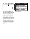
Serious shock may occur. Open primary
disconnect switch before attempting any
repairs.
W447
WARNING