


Installation
54
F232062
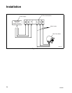
Chemical Injection Supply
System
(Continued)
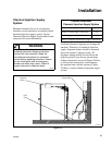
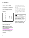
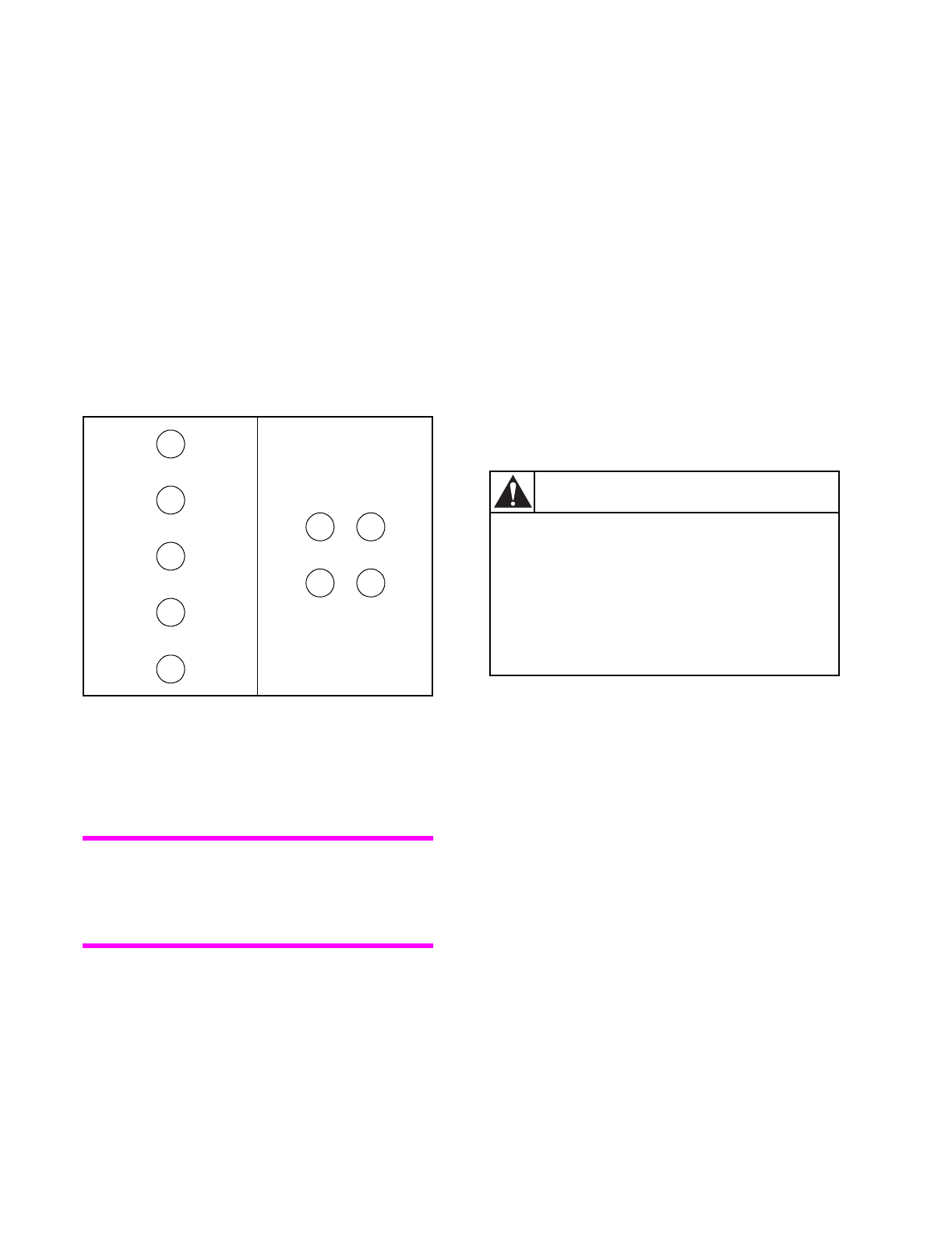
Four hose barbs (five on V-computer models)
on the rear of the machine facilitate connection
to an external chemical injection supply
system. The arrangement of the hose barbs
will form either a straight line or a box. Figure
40 indicates which hose barb corresponds to
which supply.
Figure 40
A terminal strip in the input power junction
box provides supply output signals for the
chemical injection supply system.
Note:
Do not attempt to make chemical
injection supply pump electrical connections
to points other than those provided specifically
for that purpose by the factory.
Machines connected to 200VAC provide L1
and L2 fused outputs rated at 3 amps which
may be used to power 208 – 240VAC
supply pumps.
Machines connected to 400VAC do not
provide L1 and L2 outputs. An external power
source must be provided to power the chemical
supply pump.
Do not use L1 or L2 with the common line to
deliver 120VAC to chemical injection supply
pumps if the machine is equipped with a
control transformer. The transformer will not
be able to provide enough current to operate
the control circuits and drive the chemical
supply pumps.
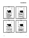
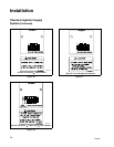
Consult the chemical injection supply system
instructions for operational details. See
Figures 41 through 47 for terminal strip decals.
1
2
3
4
5
1
2
3
4
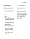
Attempting to obtain 110VAC by using L1 or
L2 with the common may damage laundry
machine circuitry and/or the chemical
injection system. Using a 240VAC power
wire in the washer-extractor and an earth
ground to obtain 110VAC could cause
microprocessor problems.
SW028
CAUTION