


Installation
34
F232062
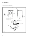
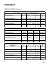
Mechanical Installation
(Continued)
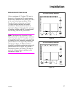
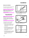
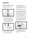
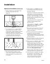
4. Drill and chisel out a conical hole large
enough to accept the J-bolt. See
Figure 24.
Figure 24
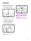
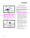
5. Use compressed air or a squeeze bulb to
remove debris from each hole. Anchor
J-bolt in place, using an industry-accepted
anchoring compound. Verify that the
J-bolts are in the correct locations and that
1-1/2 inches (38 mm) of each J-bolt
protrude from the floor. See Figure 25.
Figure 25
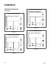
6. Raise and level the base frame 1/2 inch
(13 mm) off the floor on three points,
using spacers such as nut fasteners.
7. Fill the space between the frame base
and the floor with a good quality
non-shrinking machinery grout to ensure a
stable installation. Grout completely under
all frame members.
8. Remove the spacers carefully, allowing the
base frame to settle into the wet grout.
9. Before grout sets completely, make a drain
opening in the rear of the base frame
grouting with a stiff piece of wire. This
opening should be approximately 1/2 inch
(13 mm) wide to allow any surface water
build-up under the base of the machine to
drain away.
Do not omit this step.
10. Position washers and locknuts on J-bolts
and fingertighten nuts to machine base.
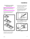
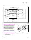
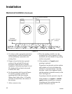
11. After the grout is completely dry, tighten
locknuts by even increments—one after
the other—until all are tightened evenly
and the base frame is fastened securely to
the floor. See Figure 26.
Figure 26
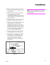
12. Position the machine over the base frame,
aligning the mounting holes on the
machine with the corresponding holes on
the frame.
H031I
H032IE1A
H033I