


© Copyright, Alliance Laundry Systems LLC – DO NOT COPY or TRANSMIT
Installation
13
803465
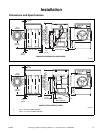
Figure 12
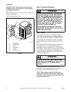
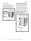
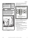
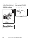
A junction box on the rear panel houses a terminal
strip which furnishes supply output signals for the
supply injection pumps. Refer to Figure 13 for the
injection interface label.
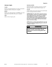
Figure 13
These terminals may be used to provide signals to the
supply injection system but must not be used to
provide power to the actual pump.
Any injection system pump which requires
110 VAC must be powered by a separate external
power source.
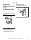
Control Function Test
The washer should be cleaned after the installation is
complete. A function test should then be executed on
the unloaded machine:
1. Check the power supply for such characteristics
as correct voltage, phase, and cycles to be certain
they are correct for the washer.
2. Open manual shut-off valves to the washer.
3. Apply power to the washer.
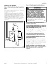
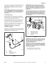
Supply Injection System
Number of liquid supply connections
(1–Detergent and 2–Softener)
2
Liquid supply connection size,
in. (mm)
3/8 (9.52)
or
1/4 (6.35)
FLW2116N
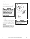
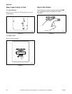
1 Injection Point
2 Nozzle
3 Supply Dispenser Pump Outlet
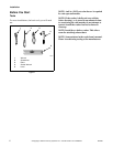
Wear eye and hand protection when
handling chemicals; always avoid direct
contact with raw chemicals. Read the
manufacturer’s directions for accidental
contact before handling chemicals. Ensure
an eye-rinse facility and an emergency
shower are within easy reach. Check at
regular intervals for chemical leaks.
SW016
WARNING
2
1
3
FLW2028N
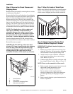
DETERGENT
DISPENSER
CONNECTION
SOFTENER
DISPENSER
CONNECTION
SOFTENER
RELAY
DETERGENT
RELAY
CHEMICAL INJECTION
ELECTRICAL INTERFACE
NO CONNECTION
TERMINAL
BLOCK
YELLOW
YELLOW/BLACK
RED
RED/BLACK
801653R1
NOTE: Normally Open Contacts.
Contacts Close to Start Chemical Injection.
Maximum Load Connection per Contact:
1A @ 120VAC/240VAC