


© Copyright, Alliance Laundry Systems LLC – DO NOT COPY or TRANSMIT
Installation
803465
12
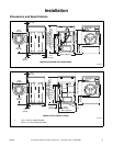
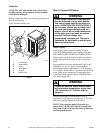
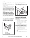
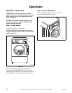
Step 6: Remove the Shock Sleeves and
Shipping Brace
Remove front access panel by removing the two screws
at the bottom of the panel.
Remove the five bolts and lockwashers from shipping
brace with 9/16 in. wrench and remove brace. Refer to
Figure 10. One is holding the brace to the weight.
Remove this bolt first. Four bolts are located on the
washer base. Remove the two front bolts next and then
the two rear bolts. Remove all four shock sleeves by
pulling on the yellow rope. Remove label from front
side of front access panel or shipping brace and place
on backside of front access panel for future reference.
NOTE: The shipping brace, bolts, washers and
shock sleeves should be saved and MUST be
reinstalled whenever the washer is moved more
than four feet. Refer to User-Maintenance section
for instructions. Do not lift or transport washer
from front or without shipping materials installed.
Store the shipping materials in the accessories bag.
Save materials for use whenever the washer is moved.
Reinstall front access panel.
IMPORTANT: DO NOT tip washer more than
6 inches (152.4 mm) in any direction after shipping
brace has been removed. Shock absorbers may
separate and damage to washer may result. For
leveling purposes, the washer may be tilted a
maximum of 6 inches (152.4 mm) in any direction.
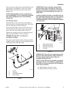
Figure 10
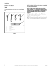
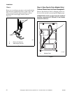
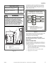
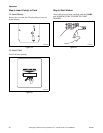
Step 7: Wipe Out Inside of Wash Drum
Before using washer for the first time, use an all-purpose
cleaner, or a detergent and water solution, and a damp
cloth to remove shipping dust from inside wash drum.
Figure 11
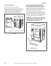
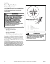
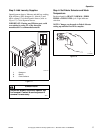
Step 8: (Supply Injection Models Only)
Connect External Supplies to Washer
IMPORTANT: Undiluted chemical dripping can
damage the washer.
1. Remove two nozzles from accessories bag. Use
either the 3/8 inch or 1/4 inch nozzles, depending
on the diameter of the dispenser tubing used.
2. Attach nozzles to rear of machine. Connection
point located on cabinet, above water mixing
valve. Refer to Figure 12.
3. Connect supply hoses to nozzles and secure with
hose clamps (obtain locally). Refer to Figure 12.
NOTE: Hoses can be connected to either nozzle.
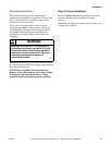
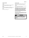
4. Refer to supply injection system instructions and
label inside washer junction box cover
(Figure 13) for electrical connection.
Do not attempt to make supply injection
electrical connections to points other than those
provided specifically for that purpose by the
factory.
5. Refer to supply injection system instructions for
details on operation.
FLW2124N
1 Shock Sleeves
2 Motor Mount
3 Hooked End of Shipping Brace
4 Bolts and Lockwashers
FLW2124N
2
1
4
3
FLW2115N
FLW2115N