


© Copyright, Alliance Laundry Systems LLC – DO NOT COPY or TRANSMIT
Installation/Operation Supplement
F232145 (EN)
8
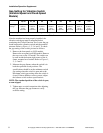
Gap Setting for Vibration Switch
(Variable-Speed and Fixed-Speed
Models)
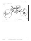
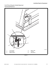
After the machine has been properly installed, the
vibration switch gap must be measured before
conducting the Control Function Test. Locate the gap
found between the vibration switch and the machine
structure. Refer to Figures 1, 2, 3, 4 and 5. To check
the gap setting of the switch, proceed as follows:
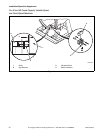
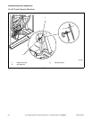
1. Remove the front panel on 18-50 models.
Remove the rear panel on 60-80 models. Remove
the top cover on the 125 model. The switch can
be seen inside the bottom right corner of the A-
frame, mounted on a bracket. Refer to Figures 1,
2, 3, 4 and 5.
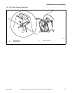
2. Measure the gap distance when the switch is in
both the open and closed positions. The
specifications should be at the minimum switch
gap setting when the switch is open and at the
maximum switch gap setting when the switch is
closed. If these distances are not correct, adjust
the balance switch to these specifications.
NOTE: The standard position of the switch is open,
or non-tripped.
3. Tighten nuts on switch extension after adjusting
the gap. Measure the gap distance to verify
accurate setting.
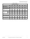
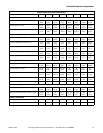
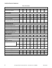
18, 20 27, 30 35 40 50 60 80 125
Switch gap
setting*
0.015-
0.025 in.
(0.38-
0.64 mm)
0.025-
0.035 in.
(0.64-
0.89 mm)
0.030-
0.040 in.
(0.76-
1.02 mm)
0.020-
0.030 in.
(0.51-
0.64 mm)
0.025-
0.035 in.
(0.64-
0.89 mm)
0.013-
0.015 in.
(0.20-
0.25 mm)
0.009-
0.011 in.
(0.23-
0.28 mm)
0.006-
0.008 in.
(0.15-
0.20 mm)
* Gap setting should be made with “GO-NO-GO” type feeler gauge. Lower value must not trip switch. Upper value must trip switch.
Table 2