5. Unscrew hinge A from the load
door and turn it through 180°, then
put on the opposite side and screw
down.
6. Turn cover plates B through 180°
and put them on the opposite side.
7. Unscrew cover plates D from the
front of the appliance, turn through
180° and screw down on the oppo-
site side.
E
E
D
D
FF
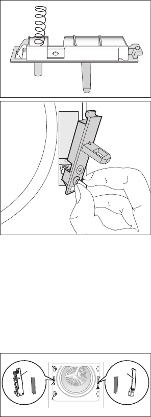
8. Unscrew door lock E, push down
lightly and remove from the front of
the appliance.
9. Push snap-in button F in and down,
push cover down lightly and re-
move from front of the appliance.
10. Change door lock E above to the
opposite side, screw down the
door interlock.
11. On the other side, put cover F and
let snap-in button to lock into posi-
tion.
12. Put load door and hinges into re-
cesses on the front of the appliance
and screw down.
Note regarding contact pro-
tection: The appliance is only
secure for operations again
once all plastic parts have been
put.
ELECTRICAL CONNECTION
• Connect the appliance to a groun-
ded socket. Refer to the applicable
electrical requirements.
• Make sure that the electrical data on
the rating plate agrees with the pow-
er supply.
• Always use a correctly installed
shockproof socket.
• Do not use multiple plugs and exten-
sion cables. There is a risk of fire.
• All replacements of power supply ca-
ble must be carried out by our Serv-
ice.
• Make sure not to squash or cause
damage to the mains plug and cable
behind the appliance.
• Do not pull the mains cable to dis-
connect the appliance. Always pull
the mains plug.
• The plug must be dry.
The data about mains voltage, type of
current and the necessary fuse are on
the rating plate and in the “TECHNI-
CAL INFORMATION” chapter. The rat-
ing plate is behind the load door (see
the “PRODUCT DESCRIPTION” chap-
ter).
The appliance has a power supply ca-
ble with plug fitted with 13 A fuse. If
necessary, replace the fuse in the plug
by 13 A ASTA BS 1363/A approved
fuse.
The wires in the power supply cable are
coloured as follow:
24


