26 American Dryer Corporation 450431-3
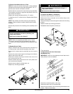
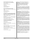
Data Label
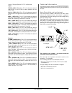
When contacting ADC, certain information is required to
ensure proper service/parts information. This information is
on the data label, located on the top right corner of the dryer,
viewed from the rear (refer to illustration). When contacting
ADC, please have the model number and serial number
readily accessible.
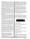
Information on the Data Label
A. Model number — The model number is an ADC number
which describes the size of the dryer and the type of
heat (gas or steam).
B. Serial number — The serial number allows ADC to gather
information on your particular dryer.
C. Manufacturing code number — The manufacturing code
number is a number issued by ADC, which describes
all possible options on your particular model.
D. Type of heat — Describes the type of heat; gas (natural
or L.P.), steam or electric.
E. Heat input — (For gas dryers) describes the heat input
in British Thermal Units.
F. Electric service — Describes the electric service for your
particular models.
G. Gas manifold pressure — Describe the manifold pressure
as taken at the gas valve pressure tap (refer to “Using a
Manometer”).
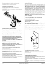
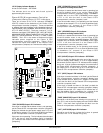
Using a Manometer
How To Use A Manometer
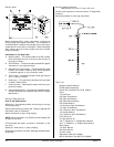
With dryer in non-operating mode, remove plug on the gas
valve pressure tap.
Attach plastic tubing to pressure tap. Fitting is supplied with
manometer (refer to illustration).
Attach manometer to dryer using magnet.
NOTE: Place manometer in a position so that readings can
be taken at eye level.
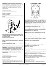
Fill manometer with water, as shown in illustration, to the
zero level.
Start dryer. With burner on, take a reading.
Read water level at the inner tube. Readings should be taken
at eye level.
Correct readings should be:
Natural Gas: 3.5 in wc; L.P. Gas: 10.5 in wc
If water column pressure is incorrect refer to “To Adjust Gas
Pressure”.
Reverse procedure for removing manometer.
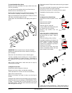
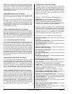
Tool List
Straight Head Screwdriver
Phillips Head Screwdriver
Sensor Pin and Socket Tool (P/N 122801)
Pliers
1/4” Nut Driver
3/8” Open End Wrench
5/8” Open End Wrench
5/8” Deep Socket Wrench
3/8” Socket Wrench
1/2” Socket or Open End Wrench
1/4” Open End Wrench
5/16” Socket or Open End Wrench
1/2” Socket Wrench
7/16” Socket or Open End Wrench
5/16” Nut Driver
12” Pipe Wrench (2)
1/8” “T” Shaped or “L” Shaped Allen Wrench
3/16” “T” Shaped or “L” Shaped Allen Wrench
Wire Cutters
1/2” Allen Wrench
3/8” Allen Wrench
Channel Locks
Manometer (ADC P/N 122804)
MP Pin Extraction Tool (ADC P/N 122800)


