17
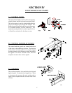
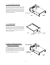
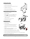
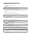
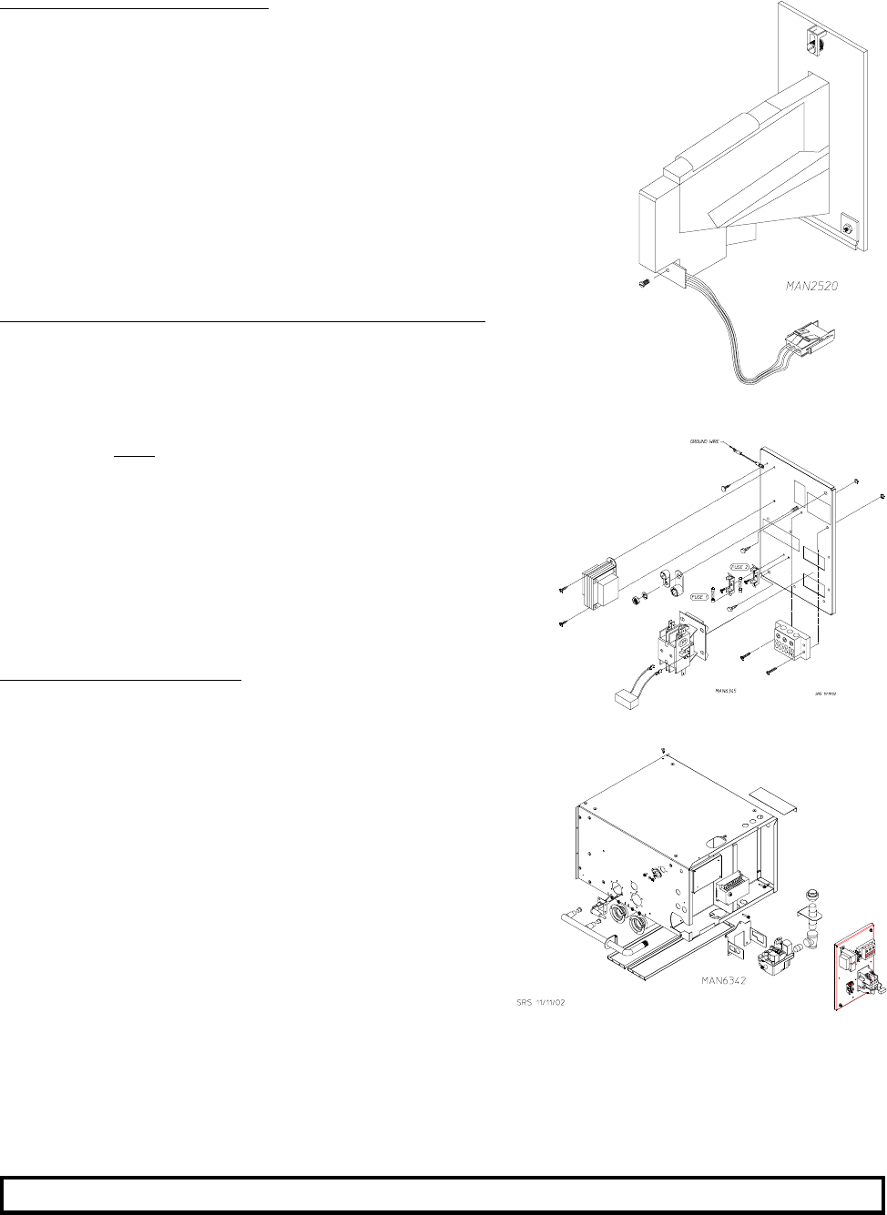
TO REMOVE OPTIC SWITCH
1. Disconnect power to the dryer.
2. Remove top or bottom coin panel.
3. Remove optic switch from the coin acceptor (one [1] screw).
4. Unplug optic switch connector.
5. Remove optic switch from the dryer.
6. Reverse procedure for installing new optic switch.
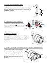
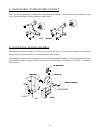
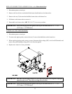
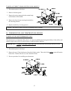
TO REPLACE MOTOR CONTACTOR 2-POLE, 24 VAC
1. Discontinue power to the dryer.
2. Remove back guard.
3. Remove
ALL wires from contactor (NOTE: Make sure
each wire is marked with location removed from).
4. To remove the contactor, push up and pull the
contactor towards you.
5. Install new contactor in reverse procedure.
6. Reestablish power to the dryer.
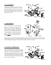
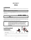
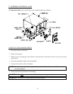
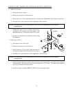
TO REPLACE GAS VALVE
1. Discontinue power to the dryer.
2. Remove back guard.
3. Close the union shutoff located just before the gas valve
and remove the two (2) wires on top of the gas valve.
4. Break and loosen union nut between union shutoff and
gas valve.
5. Remove the four (4) screws holding the two (2) pipe
brackets on each side of the gas valve.
6. Remove gas valve and manifold (still attached) from dryer.
7. Remove the single port manifold from the output side of the gas valve.
8. Remove the union tailpiece and nut from the input of valve. (A 1/2” Allen wrench is required.)
9. Reverse procedure for installing new valve.
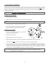
IMPORTANT: Pipe dope must be applied to manifold before installing it into new valve.


