Users Manual TOPAS900 Flash V2.1
HWU Elektronik Oberhausen Page 33
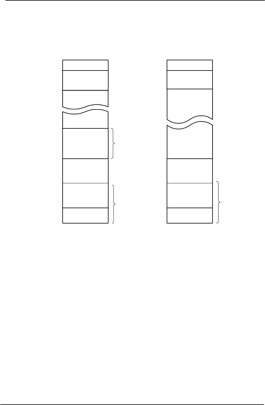
Internal RAM
(8K bytes)
Internal I/O
(160 bytes)
000000H
0000A0H
0020A0H
FC0000H
external memory
external memory
FFFF00H
Vector table
(256 bytes)
FFFFFFH
MEMORY MAP
Boot Memory : internal ROM
Reset-Conditions :
/EA = H
/BOOT = H
Internal Flash ROM
(256K bytes)
ROMSTART*
External Flash Memory
(512 K bytes)
Internal RAM
(8K bytes)
Internal I/O
(160 bytes)
000000H
0000A0H
0020A0H
external memory
external memory
FFFF00H
Vector table
(256 bytes)
FFFFFFH
MEMORY MAP
Boot Memory : external ROM
Reset-Conditions :
/EA = L
/BOOT = H
External Flash Memory
(512 K bytes)
F80000H
* ROMSTART is programmed by CS2 registers
* RAMSTART is programmed by CS1 registers
ext.
ROM
ext.
ROM
External RAM
(128 K bytes)
RAMSTART*
External RAM
(128 K bytes)
RAMSTART*
int.
ROM
Figure 13 : Memory Map for using external / internal Flash
For programming the external flash the /EA line has to be set High which can be derived
by opening the jumper J_EA (see fig. 1 at the right top and in the schematic fig. 10 at the
bottom in the middle). The map of fig. 7 is valid and the external flash can be
programmed supported by the 8-bit controller.
For normal operation and debugging it is important that the system starts from external
flash, i.e. the vector table and the firmware have to be located and to be started from there.
Like shown in the map of fig. 8 the external flash is located from off address F80000h to
FFFFFFh including the vector area.
For running in normal operation the jumper J_EA can be left open, because the /EA line
is controlled by the firmware controller. If the Flash Carrier Board works stand-alone
(without Programming-and-Debugging Board), the jumper must be set when external


