Chapter 2: Installation
2-29
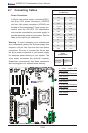
F1
BMC CTRL
LAN CTRL
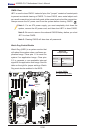
BIOS
FP CTRL
A1
COM1
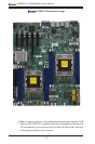
1.10Rev.
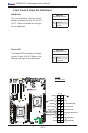
X9DRD-iF
JBT1
LED2
LEDM1
LED3
JIPMB1
JD1
JUIDB
JPW4
SP1
JSTBY1
JRK1
JPW3
JPW2
JPW1
JBAT1
JL1
JOH1
JI2C2
JI2C1
JWD1
JPG1
JPB1
JPL1
FAN4
FAN5
FAN6
FAN2
FAN1
FAN8
FAN7
T-SGPIO2
T-SGPIO1
SCU0
I-SATA2
I-SATA1
I-SATA0
JF1
JTPM1
G1
H1
E1
C1
D1
USB6
USB4/5
USB8/9
CPU1
CPU1
SLOT7 PCI-E 3.0 X8
CPU2
CPU2
CPU1
B1
SLOT4 PCI-E 3.0 X8
SLOT3 PCI-E 3.0 X8
SLOT5 PCI-E 3.0 X8
SLOT6 PCI-E 3.0 X16
COM2
VGA
LAN2
LAN1
USB2/3
IPMI_LAN
USB0/1
JPME1
LAN
CTRL
BMC
CLK CTRL
JVR1
JVR2
JVRM_I2C2
JVRM_I2C1
PCH
JSD1
I-SATA3
I-SATA4
I-SATA5
SCU1
SCU2
SCU3
S-SGPIO1
FAN3
JPW5
JPI2C1
+
:OH LED
JPME2
CPU1
CPU2
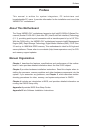
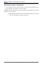
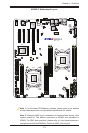
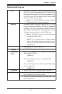
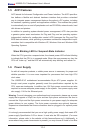
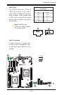
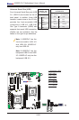
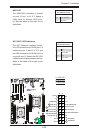
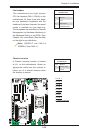
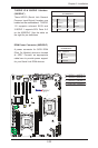
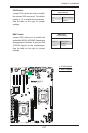
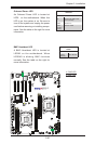
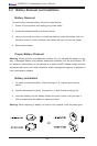
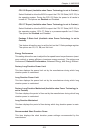
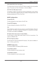
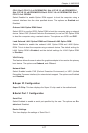
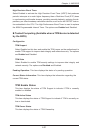
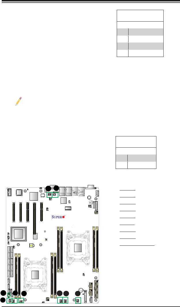
Chassis Intrusion
A Chassis Intrusion header is located
at JL1 on the motherboard. Attach an
appropriate cable from the chassis to
inform you of a chassis intrusion when
the chassis is opened.
Chassis Intrusion
PinDenitions
Pin# Denition
1 Intrusion Input
2 Ground
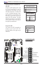
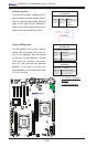
C
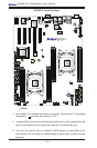
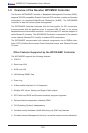
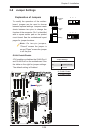
A. Fan 1
B. Fan 2
C. Fan 3
D. Fan 4
E. Fan 5
F. Fan 6
G. Fan 7
H. Fan 8
I. Chassis Intrusion
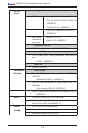
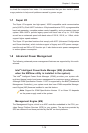
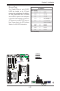
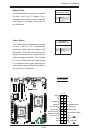
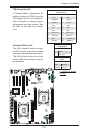
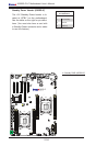
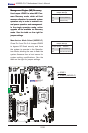
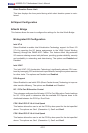
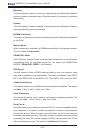
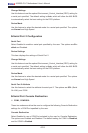
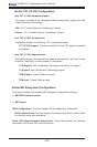
Fan Headers
This motherboard has eight system/
CPU fan headers (FAN 1~FAN 8) on the
motherboard. All these 4-pin fans head-
ers are backward compatible with the
traditional 3-pin fans. However, fan speed
control is available for 4-pin fans only.
The fan speeds are controlled by Thermal
Management via Hardware Monitoring in
the Advanced Setting in the BIOS. (See
Chapter 4 for more details.) See the table
on the right for pin denitions.
Fan Header
PinDenitions
Pin# Denition
1 Ground
2 +12V
3 Tachometer
4 PWR Modulation
A
B
I
H
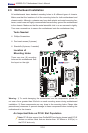
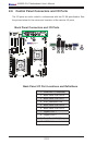
Note: X9DRD-iF has FAN1~8.
X9DRD-LF has FAN1~6.