2-28
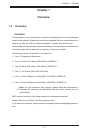
X9DRD-iF/LF Motherboard User’s Manual
F1
BMC CTRL
LAN CTRL
BIOS
FP CTRL
A1
COM1
1.10Rev.
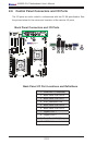
X9DRD-iF
JBT1
LED2
LEDM1
LED3
JIPMB1
JD1
JUIDB
JPW4
SP1
JSTBY1
JRK1
JPW3
JPW2
JPW1
JBAT1
JL1
JOH1
JI2C2
JI2C1
JWD1
JPG1
JPB1
JPL1
FAN4
FAN5
FAN6
FAN2
FAN1
FAN8
FAN7
T-SGPIO2
T-SGPIO1
SCU0
I-SATA2
I-SATA1
I-SATA0
JF1
JTPM1
G1
H1
E1
C1
D1
USB6
USB4/5
USB8/9
CPU1
CPU1
SLOT7 PCI-E 3.0 X8
CPU2
CPU2
CPU1
B1
SLOT4 PCI-E 3.0 X8
SLOT3 PCI-E 3.0 X8
SLOT5 PCI-E 3.0 X8
SLOT6 PCI-E 3.0 X16
COM2
VGA
LAN2
LAN1
USB2/3
IPMI_LAN
USB0/1
JPME1
LAN
CTRL
BMC
CLK CTRL
JVR1
JVR2
JVRM_I2C2
JVRM_I2C1
PCH
JSD1
I-SATA3
I-SATA4
I-SATA5
SCU1
SCU2
SCU3
S-SGPIO1
FAN3
JPW5
JPI2C1
+
:OH LED
JPME2
CPU1
CPU2
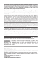
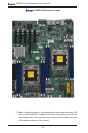
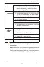
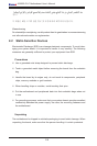
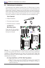
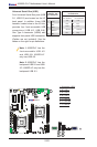
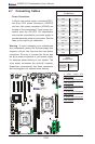
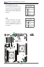
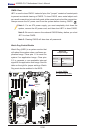
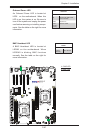
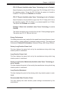
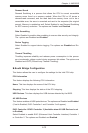
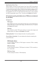
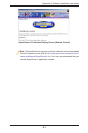
Warning: To avoid damaging your motherboard
and components, please use a power supply that
supports a 24-pin, two 4-pin and two 8-pin power
connectors. Be sure to connect the 24-pin and
the 8-pin power connectors to your power supply
for adequate power delivery to your system. The
4-pin power connectors are optional; however,
Supermicro recommends that these connectors
also be plugged in for optimal power delivery.
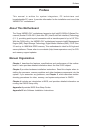
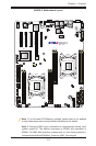
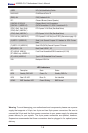
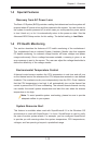
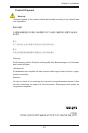
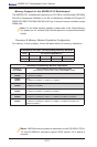
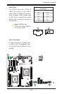
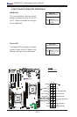
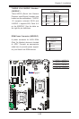
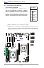
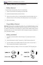
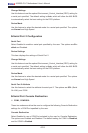
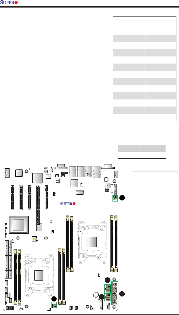
2-7 Connecting Cables
Power Connectors
A 24-pin main power supply connector(JPW1),
two 8-pin CPU power connectors (JPW2/3)
and two 4-pin power connectors (JPW4/5) are
located on the motherboard. These power con-
nectors meet the SSI EPS 12V specication
and must be connected to your power supply to
provide adequate power to the system. See the
table on the right for pin denitions.
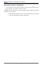
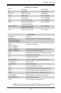
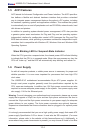
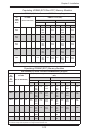
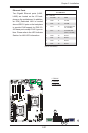
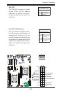
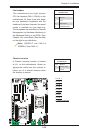
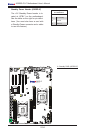
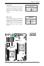
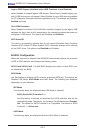
ATX Power 24-pin Connector
PinDenitions
Pin# Denition Pin # Denition
13 +3.3V 1 +3.3V
14 -12V 2 +3.3V
15 COM 3 COM
16 PS_ON 4 +5V
17 COM 5 COM
18 COM 6 +5V
19 COM 7 COM
20 Res (NC) 8 PWR_OK
21 +5V 9 5VSB
22 +5V 10 +12V
23 +5V 11 +12V
24 COM 12 +3.3V
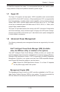
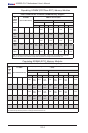
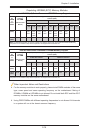
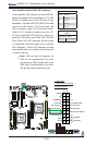
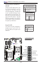
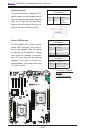
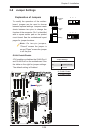
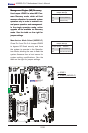
12V 8-pin PWR Con-
nector
PinDenitions
Pins Denition
1 through 4 Ground
5 through 8 +12V
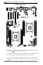
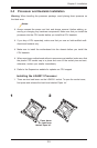
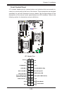
A. JPW1: 24-pin ATX
PWR (Req'd)
B. JPW2: 8-pin Processor
PWR (Req'd)
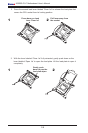
C. JPW3: 8-pin Processor
PWR (Req'd)
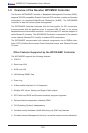
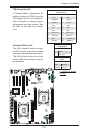
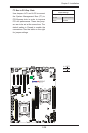
D. JPW4: 4-pin Processor
PWR (Req'd)
E. JPW5: 4-pin Processor
PWR (Req'd)
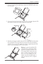
A
B
C
(Required)