2-22
X6DH3-G2/X6DHi-G2 User's Manual
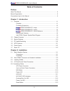
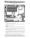
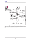
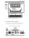
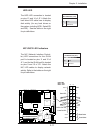
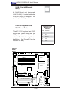
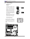
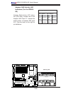
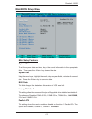
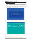
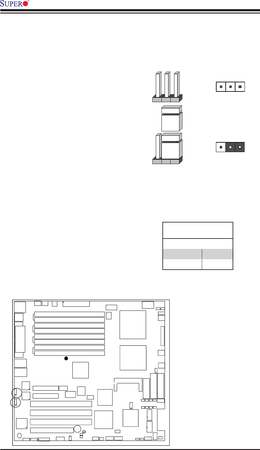
2-6 Jumper Settings
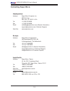
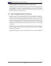
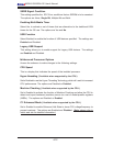
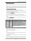
Explanation of
Jumpers
To modify the operation of the
motherboard, jumpers can be
used to choose between optional
settings. Jumpers create shorts
between two pins to change the
function of the connector. Pin 1 is
identifi ed with a square solder pad
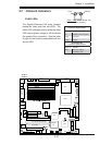
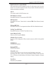
on the printed circuit board. See
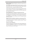
the motherboard layout pages for
jumper locations.
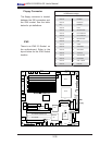
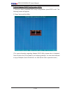
Note: On two pin jumpers, "Closed"
means the jumper is on and "Open"
means the jumper is off the pins.
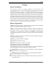
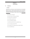
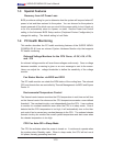
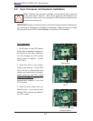
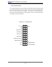
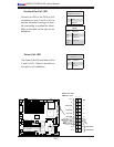
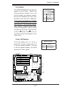
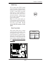
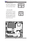
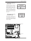
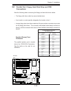
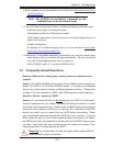
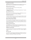
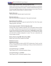
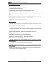
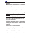
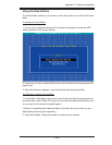
GLAN Enable/Disable
JPL1/JPL2 enables or disables the
GLAN port(s) on the motherboard.
See the table on the right for jumper
settings. The default setting is en-
abled.
GLAN 1 Enable
GLAN 2 Enable
Connector
Pins
Jumper
Setting
3 2 1
3 2 1
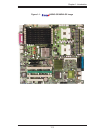
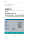
LAN1
®
JLAN1
S
UPER X6DH3-G2
LAN2
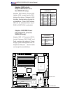
DIMM 2A
DIMM 2B
DIMM 3A
DIMM 3B
DIMM 4
A
DIMM 4B
DIMM 1B
DIMM 1A
12V 8-pin
PWR
JF
1
FP Control
JOH
IPMI
ID
E2
Floppy
BI
OS
Fan4
SMB
PC
I-X100 MHz
PC
I-X 100 MHz Z
C
R (Gree
n
Slo
t)
PC
I-
X 13
3 MH
z
B
a
ttery
JPL1
PC
I-E
X8
VGA
COM1
U
SB
0/
1
KB/M
S
F
an6
F
an5
A
T
X PWR
12V 4-Pin
PWR
Parrallel
Port
24-P
in
Fan7
JPW1
Fan8
CP
U
1
S
I/O
PSF
Fan3
ID
E
1
PC
I-33 MH
z
U
SB2
/
3
ICH
J
PG
1
J
WD
Slo
t1
Slot2
Slo
t3
Slo
t4
Slo
t5
Slot6
PCI-
E
X8
GLAN
C
T
RL
6300ESB
Buzzer
P
X
H
JBT1
I-SATA1
GLAN
C
T
RL
JPL2
JL1
J
PS1
SAS
C
T
RL
F
an2
Fan1
JAR
J
3P
CP
U
2
E7520
Bank1
Bank2
Bank3
Bank4
WOL
SEPC
COM2
SMB P
S
JWO
R
JS10
VG
A
CT
RL
JD1
JI
2
C2
I-SATA0
DS5
DS6
DS7
DS8
DS1
DS2
DS3
DS4
SAS4-7
SAS0-3
JSM1
JS9
JP9
J1D1
J32
J38
J
33
J14
J7
JLAN1
JLAN2
JI
2
C
1
J31
JSM2
JP1
GLAN Enable
Jumper Settings
Jumper Setting Defi nition
Pins 1-2 Enabled
Pins 2-3 Disabled