1-4
X6DH3-G2/X6DHi-G2 User's Manual
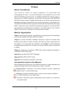
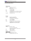
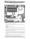
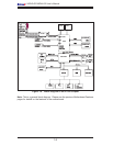
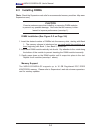
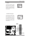
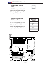
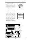
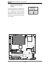
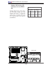
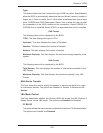
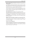
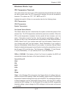
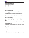
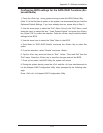
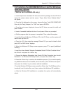
Notes:
1. Jumpers not indicated are for testing only.
2. See Chapter 2 for detailed information on jumpers, I/O ports and JF1 front panel
connections.
3. " " indicates the location of Pin 1.
4. For RAID to function properly, please install the ZCR Card in the Green PCI
slot.
5. When the Onboard Standby PWR LED Indicator is on, it indicates that the Power
and the system is on. Do not remove or install any components without turning off
the system and disconnecting the AC power.
6. The drawings and pictures shown in this manual were based on the latest
PCB Revision available at the time of publishing of the manual. The motherboard
you've received may or may not look exactly the same as the graphics shown in
the manual.
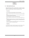
7. All components related to SAS: SAS Controller, SAS 0-3, SAS 4-7 Connectors,
SAS LEDs: DS 1-8, JS9, JS10 and JPS1 are for the X6DH3-G2 only.
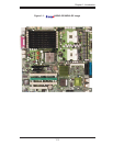
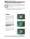
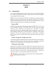
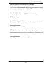
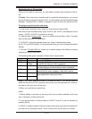
Figure 1-2. X6DH3-G2/X6DHi-G2 Motherboard Layout
(not drawn to scale)
LAN1
®
JLAN1
S
UPER X6DH3-G2
LAN2
DIMM 2A
DIMM 2B
DIMM 3A
DIMM 3B
DIMM 4A
DIMM 4B
DIMM 1B
DIMM 1A
12V 8-pin
PWR
JF1
FP Control
JOH
IPMI
IDE2
Floppy
BIOS
Fan4
SMB
PCI-X1
00 MHz
PCI-X 100 MHz ZCR (Green
Slot)
PCI-X 133 MHz
B
attery
JPL1
PCI-E X8
VGA
COM1
USB
0/1
KB/MS
Fan6
Fan5
ATX PWR
12V 4-Pin
PWR
Parrallel
Port
24-Pin
Fan7
JPW1
F
an8
CPU1
S I/
O
PSF
Fan3
IDE1
PCI-33 MHz
USB2/3
ICH
J
PG1
JWD
Slo
t1
Slot2
Slot3
Slot4
Slot5
Slot6
PCI-E X8
GLAN
CTRL
6300ESB
Buzzer
PXH
JBT1
I-SAT
A1
GLAN
CTRL
JPL2
JL1
JPS1
SAS
C
TRL
F
a
n2
Fan1
JAR
J3P
CPU
2
E7520
Bank1
Bank2
Bank3
Bank4
WOL
SEPC
COM2
SMB PS
JWOR
JS10
V
GA
CTRL
JD1
J
I
2
C2
I-SAT
A0
DS5
DS6
DS7
DS8
DS1
DS2
DS3
DS4
SAS4-7
SAS0-3
JSM1
JS9
JP9
J1D1
J32
J38
J33
J14
J7
JLAN1
J
LAN2
J
I
2
C1
J31
JSM2
JP1