Chapter 2: Installation
2-9
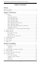
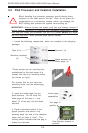
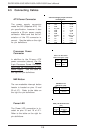
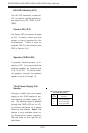
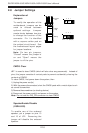
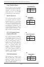
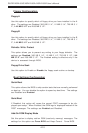
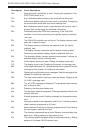
Overheat LED (OH)
Connect an LED to the OH connec-
tion on pins 7 and 8 of JF1 to pro-
vide advanced warning of chassis
overheating. Refer to the table on
the right for pin definitions.
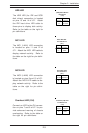
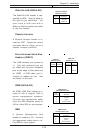
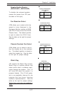
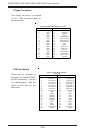
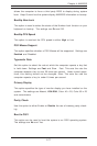
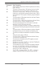
NIC1 LED
The NIC1 (LAN1) LED connection
is located on pins 11 and 12 of
JF1. Attach the NIC1 LED cable to
display network activity. Refer to
the table on the right for pin defini-
tions.
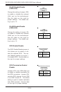
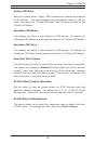
NIC/LAN2 LED
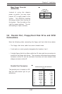
Pin Definitions
(JF1)
Pin
Number
9
10
Definition
+5V
GND
Overheat (OH) LED
Pin Definitions
(JF1)
Pin
Number
7
8
Definition
+5V
GND
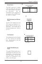
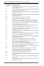
NIC2 LED
The NIC2 (LAN2) LED connection
is located on pins 9 and 10 of JF1.
Attach the NIC2 LED cable to dis-
play network activity. Refer to the
table on the right for pin defini-
tions.
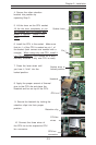
NIC/LAN1 LED
Pin Definitions
(JF1)
Pin
Number
11
12
Definition
+5V
GND
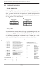
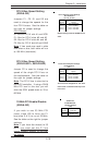
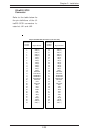
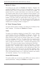
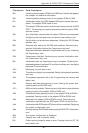
HDD LED
The HDD LED (for IDE and SCSI
disk drives) connection is located
on pins 13 and 14 of JF1. Attach
the IDE hard drive LED cable to
these pins to display disk activity.
Refer to the table on the right for
pin definitions.
(IDE) HDD LED Pin
Definitions
(JF1)
Pin
Number
13
14
Definition
+5V
HD Active