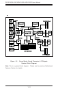
2-8
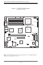
SUPER X5DL8-GG/X5DLR-8G2+/X5DLR-8G2 User’s Manual
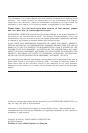
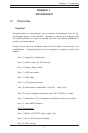
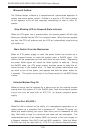
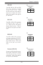
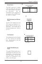
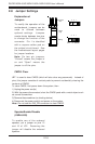
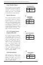
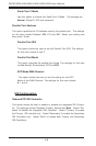
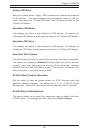
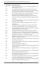
Power LED
The Power LED connection is lo-
cated on pins 15 and 16 of JF1.
Refer to the table on the right for
pin definitions.
Pin
Number
15
16
Definition
+5V
Control
PWR_LED Pin Definitions
(JF1)
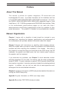
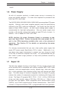
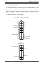
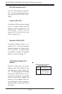
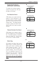
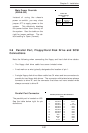
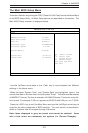
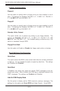
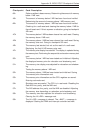
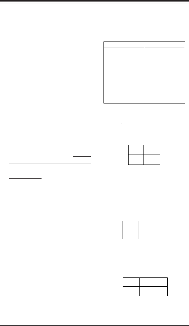
ATX Power Supply 24-pin Connector
Pin Definitions
Pin Number Definition
13 +3.3V
14 -12V
15 COM
16 PS_ON#
17 COM
18 COM
19 COM
20 Res(NC)
21 +5V
22 +5V
23 +5V
24 COM
Pin Number Definition
1 +3.3V
2 +3.3V
3 COM
4 +5V
5 COM
6 +5V
7 COM
8 PWR_OK
9 5VSB
10 +12V
11 +12V
12 +3.3V
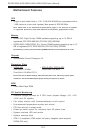
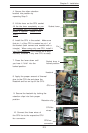
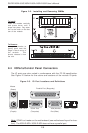
2-5 Connecting Cables
ATX Power Connector
The power supply connector
meets the SSI (Superset ATX) 24-
pin specification, however it also
supports a 20-pin power supply
connector. Make sure that the ori-
entation of the PS connector is
correct. See the table on the right
for pin definitions.
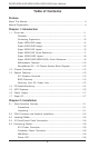
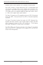
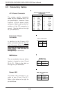
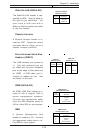
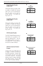
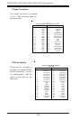
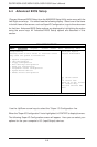
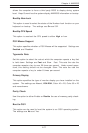
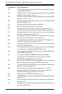
Pins
1 thru 4
5 thru 8
Definition
Ground
+12v
8-Pin +12v Processor
Power Connector (J56)
Processor Power
Connector
In addition to the Primary ATX
power connector (above), the 12v
8-pin Processor Power Connector
must also be connected to your
power supply. See the table on
the right for pin definitions.
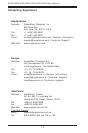
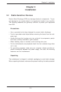
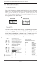
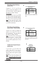
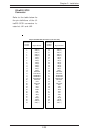
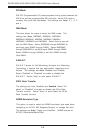
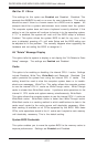
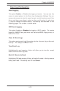
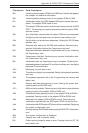
NMI Button
The non-maskable interrupt button
header is located on pins 19 and
20 of JF1. Refer to the table on
the right for pin definitions.
Pin
Number
19
20
Definition
Control
Ground
NMI Button Pin
Definitions (JF2)