Page 22
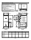
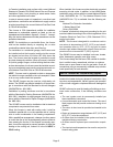
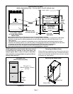
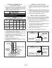
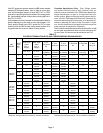
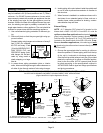
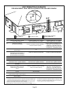
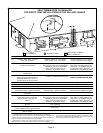
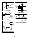
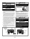
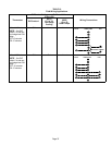
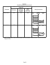
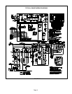
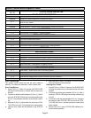
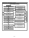
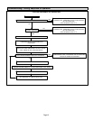
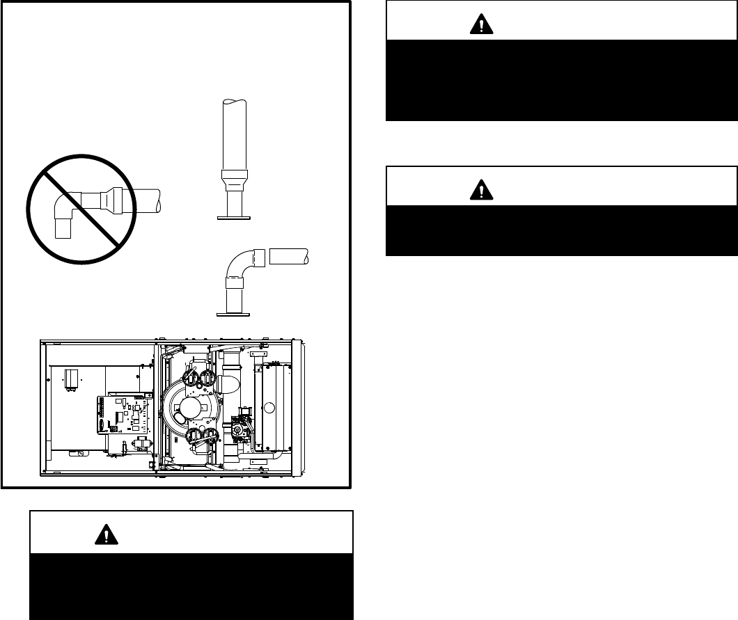
FIGURE 24
TYPICAL EXHAUST PIPE CONNECTIONS
HORIZONTAL DIRECT OR NON−DIRECT VENT
APPLICATIONS
(Horizontal Right−Hand Air
Discharge Application Shown)
2"
2"
2"
*2"
2−1/2",
3", OR
4"
DO NOT transition
from smaller to larger
pipe size in horizontal
runs of exhaust pipe.
TRANSITION
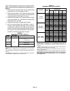
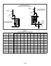
36B−045
36B−070
36B−071
48C−090
60C−090
60C−091
48C−110
60C−110*
60C−111*
60D−135*
36B−045
36B−070
36B−071
36C−090
60C−090
60C−091
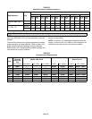
* 2" maximum length
for −110, −111 −135 only
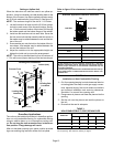
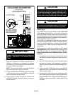
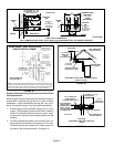
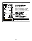
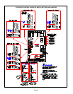
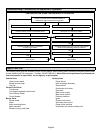
IMPORTANT
Exhaust piping and condensate trap must be
installed on the same side of the unit in upflow and
dowflow applications or use alternate drain kit
76M20.
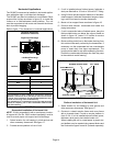
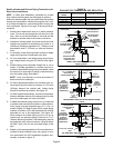
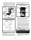
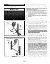
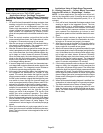
2 − All horizontal runs of exhaust pipe must slope back to-
ward unit. A minimum of 1/4" (6mm) drop for each 12"
(305mm) of horizontal run is mandatory for drainage.
Horizontal runs of exhaust piping must be supported ev-
ery 5 feet (1.52m) using hangers.
NOTE − Exhaust piping should be checked carefully to
make sure there are no sags or low spots.
3 − On the opposite side of the cabinet, glue the provided
2" ABS vent plug into the unused ABS flue collar with
ABS or all purpose solvent cement.
4 − Route piping to outside of structure. Continue with
installation following instructions given in piping ter-
mination section.
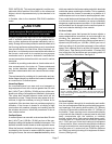
CAUTION
Do not discharge exhaust into an existing stack or
stack that also serves another gas appliance. If verti-
cal discharge through an existing unused stack is re-
quired, insert PVC pipe inside the stack until the end
is even with the top or outlet end of the metal stack.
CAUTION
The exhaust vent pipe operates under positive pres-
sure and must be completely sealed to prevent leak-
age of combustion products into the living space.
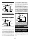
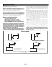
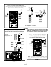
Intake Piping
The G61MP furnace may be installed in either direct vent
or non−direct vent applications. In non−direct vent applica-
tions, when intake air will be drawn into the furnace from the
surrounding space, the indoor air quality must be consid-
ered and guidelines listed in Combustion, Dilution and Ven-
tilation Air section must be followed.
The G61MP unit is designed for either left−side or right−side
air intake connections in either upflow or downflow applica-
tions. In horizontal applications, air intake must be brought
in through the top. Intake air piping is independent of ex-
haust piping.
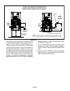
Follow the next four steps when installing the unit in direct
vent applications, where combustion air is taken from out-
doors and flue gases are discharged outdoors. The pro-
vided air intake screen must not be used in direct vent ap-
plications.
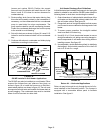
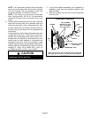
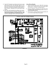
1 − Use transition solvent cement to connect PVC pipe to
the ABS slip connector located on the side of the burn-
er box.
2 − Use a #7 sheet metal screw to secure the intake pipe to
the connector, if desired. A pilot indentation is provided in
the slip connector to assist in locating and starting the fas-
tener.
3 − Glue the provided 2" ABS plug into the unused ABS air
intake connector on the opposite side of the cabinet with
ABS all pupose cement.
4 − Route piping to outside of structure. Continue with instal-
lation following instructions given in general guide lines for
piping terminations and in intake and exhaust piping ter-
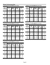
minations for direct vent sections. Refer to figure 25 for
pipe sizes.