MODEL 66-80 VIBRATORY DRIVER/EXTRACTOR
VIII. ORDERING PARTS
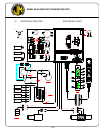
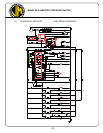
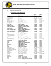
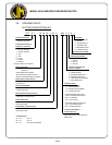
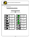
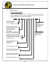
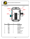
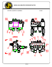
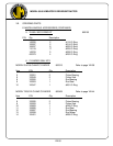
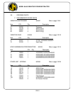
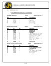
D. PARTS IDENTIFICATION
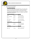
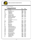
1. Parts lists and drawings are included on the following pages for the equipment
components shown below:
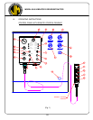
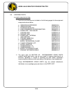
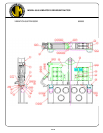
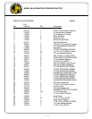
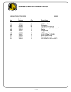
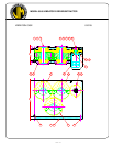
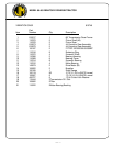
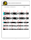
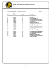
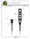
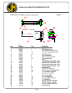
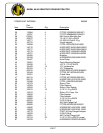
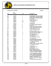
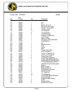
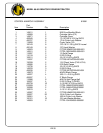
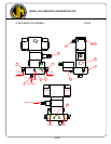
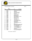
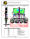
a. VIBRATION SUPPRESSOR 800503VIII-6
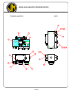
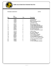
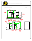
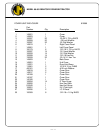
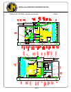
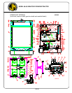
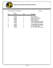
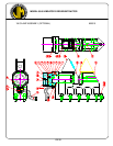
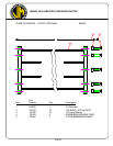
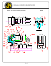
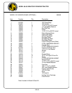
b. VIBRATION CASE 810749VIII-10
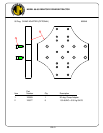
c. DISTRIBUTION BLOCK 810751VIII-12
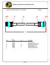
d. HOSE ASSEMBLIES-INTERCONNECTING 800405VIII-14
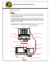
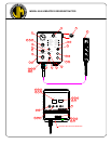
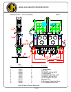
e. POWER UNIT - ENCLOSURE 810589VIII-16
f. CONTROL BOX 810593VIII-18
g. PENDANT ASM 800395VIII-22
h. POWER UNIT - INTERNAL 800385VIII-24
i. JUNCTION BOX 810145VIII-33
j. CONTROL MANIFOLD 810591VIII-34
k. CLAMP MANIFOLD 810449VIII-36
l. MODEL 196 UNIVERSAL CLAMP 800315VIII-38
m. CLAMP EXTENSION-10FT. 800423VIII-40
n. 90 DEG. ADAPTER 800049VIII-41
o. CAISSON BEAM-7 FT. 800517VIII-42
p. CAISSON BEAM-11 FT. 800519VIII-43
q. MODEL 122 CAISSON CLAMP 800409VIII-44
r. PENDANT EXTENSION CABLE 800059VIII-47
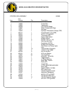
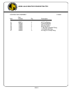
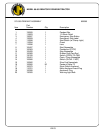
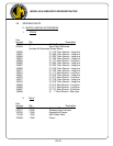
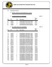
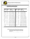
2. The spare parts list SECTION VIII - RECOMMENDED SPARE PARTS
contains spare parts which may be very useful in keeping down-time to a
minimum, especially in remote or secluded job sites where unforeseen
communication problems could cause delay of the delivery of an awaited part.
These RECOMMENDED SPARE PARTS may be ordered beforehand,
individually or as a package group as shown in the PARTS LIST.
VIII-5