MODEL 66-80 VIBRATORY DRIVER/EXTRACTOR
II. PREPARATION FOR OPERATION
B. SAFETY PRECAUTIONS (CONTINUED)
38. Never clamp vibrator to pile and disconnect the crane line. Loss of hydraulic
pressure could cause vibrator to fall. Lay vibrator down when not in use.
39. When extracting piles, always attach a safety line between pile and crane
hook.
40. When extracting piles, check crane load/radius tables to be sure crane
capacity is adequate for maximum allowable extraction pull.
41. When extracting piles, or any other driving operations, always be sure that the
crane line is aligned with the centerline of the pile. Do not side load crane
boom or vibrator. Dangerous crane boom, or vibrator, damage may result.
42. When extracting piles, do not exceed the capacity of the vibrator suppressor.
Continued operation against the safety stops will cause damage to the crane
boom and the vibrator.
43. Never induce line pull on a vibrator before starting the unit in vibration. Always
start both driving and extraction of piles with a slack line.
44. Keep hands away from clamp jaws.
45. Keep hands away from vibrator suppressor during operation. Clearances may
change causing pinch points.
46. Do not run vibrator unless clamp jaws are closed.
47. Use tag line to control vibrator whenever possible.
48. When driving “batter” piles, insure that the leads, and crane boom, have
sufficient bending strength to handle the worst case load. Consult J&M.
REMEMBER, SAFETY IS EVERYONE’S BUSINESS.
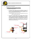
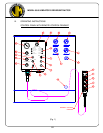
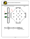
C. RIGGING OF VIBRATOR
A steel wire rope sling must be connected to the lifting pin of the vibration
suppressor. The required strength of this sling depends on the capacity of the
crane and the work to be carried out. A safety factor of five is recommended, (5 x
80 ton). Several turns of a smaller diameter cable will usually last longer than one
turn of a larger diameter cable. Inspect daily for damage to sling or wire rope
clamps.
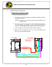
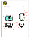
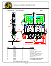
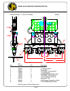
D. CONNECTION OF HYDRAULIC CLAMP
The vibrator is usually shipped with the hydraulic clamp already attached.
If the clamp is not attached, it will be necessary to attach it to the bottom of the
vibrator. Orient the clamp to the vibrator with the clamp cylinder end (movable
jaw) at the same end of the vibrator at which the hose chute is mounted. All
eleven (1.5-6UNC x 5.00lg) bolts must be in place and torqued to approximately
2800 ft-lbs. (387 Kg-M)
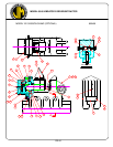
For caisson work, the caisson beam must be attached to the bottom of the vibrator
and tightened as above. Then slide the clamps into position onto the beam.
II-2