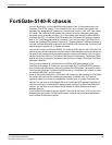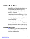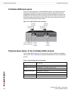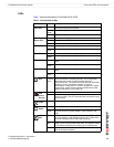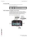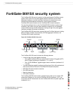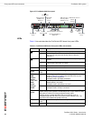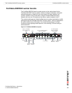
FortiGate-5140 chassis back panel FortiGate-5140 chassis
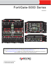
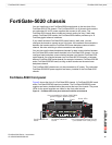
FortiGate-5000 Series Introduction
20 01-30000-83466-20090108
http://docs.fortinet.com/ • Feedback
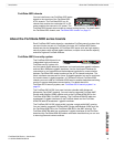
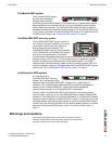
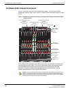
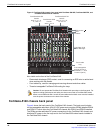
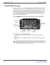
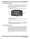
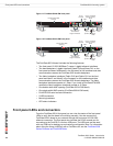
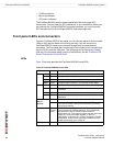
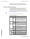
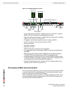
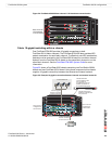
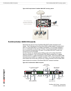
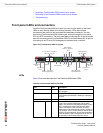
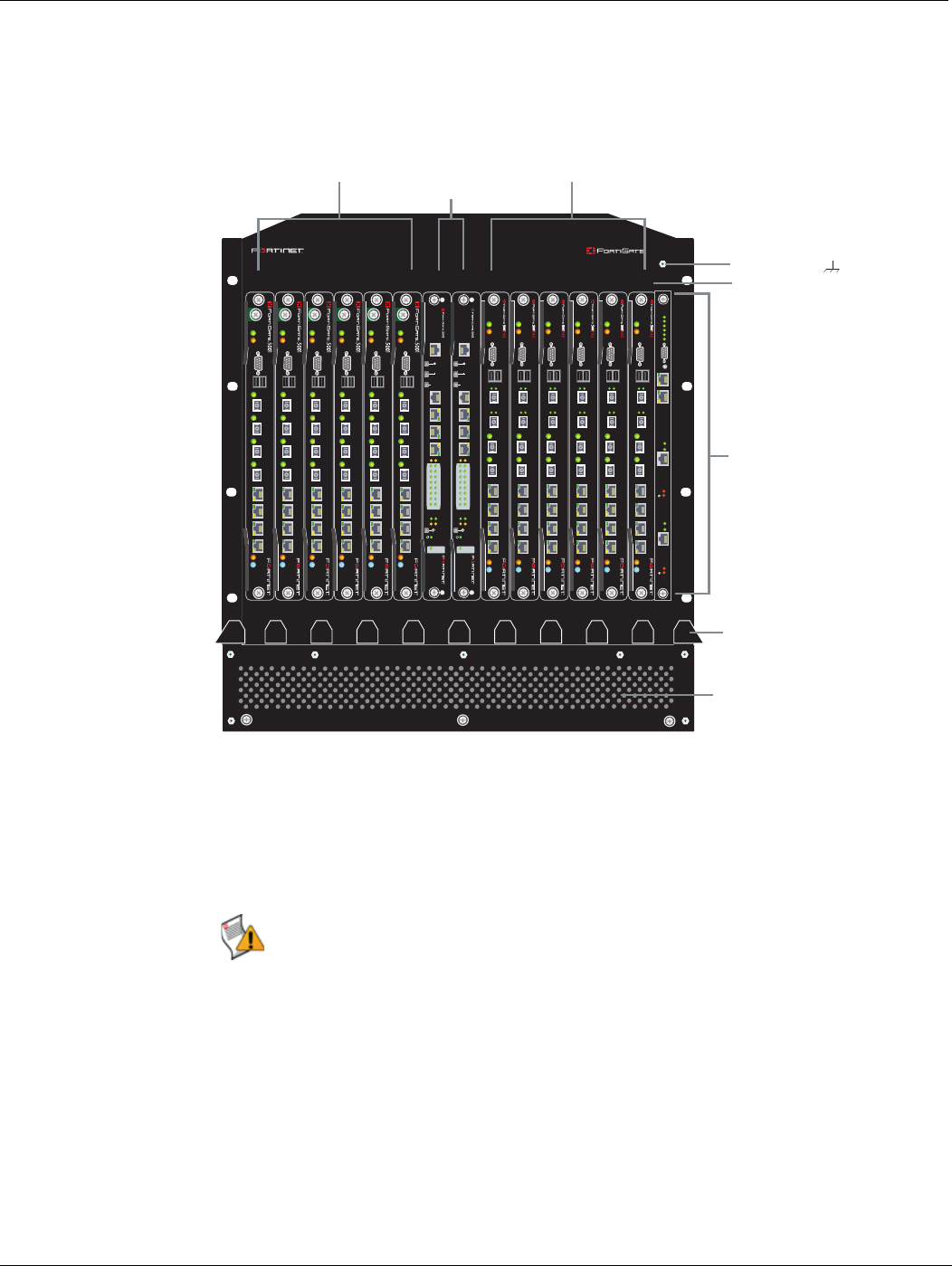
Figure 3: FortiGate-5140 chassis front panel with FortiGate-5001SX, FortiGate-5001FA2, and
FortiSwitch-5003 boards installed
Also visible on the front of the FortiGate-5140:
• Electrostatic discharge (ESD) socket, used for connecting an ESD wrist or ankle band
when working with the chassis.
• Front cable tray, used for managing and securing ethernet and other cables.
• Three hot swappable FortiGate-5140 cooling fan trays.
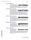
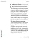
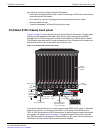
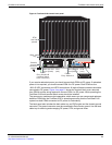
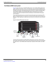
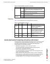
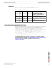
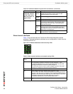
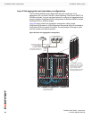
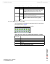
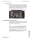
FortiGate-5140 chassis back panel
Figure 4 shows the back panel of the FortiGate-5140 chassis. The back panel includes
two hot-swappable redundant -48V/-60 VDC power entry modules (PEMs) labelled PEM A
and PEM B. Fortinet ships the FortiGate-5140 chassis with PEM A and PEM B installed.
The PEMs provide redundant DC power connections for the FortiGate-5140 chassis and
distribute DC power to the fan trays and to the FortiGate-5000 series boards installed in
the FortiGate-5140 chassis.
13 11 9 7 5 3 1 2 4 6 8 10 12 14
PWR
STAIPM
CONSOLE
USB
1 2 3 4 5 6 7 8
ACC
PWR
STAIPM
CONSOLE
USB
1 2 3 4 5 6 7 8
ACC
PWR
STAIPM
CONSOLE
USB
1 2 3 4 5 6 7 8
ACC
PWR
STAIPM
CONSOLE
USB
1 2 3 4 5 6 7 8
ACC
PWR
STAIPM
CONSOLE
USB
1 2 3 4 5 6 7 8
ACC
PWR
STAIPM
CONSOLE
USB
1 2 3 4 5 6 7 8
ACC
MANAGEMENT
SYSTEM
E1
ZRE
LED MODE
1514
1312
1110
98
76
54
32
10
E2
OKCLK
INTEXT
FLT
HOT SWAP
RESET
FLT
CONSOLE
E
T
H
O
R
S
2
3
2
Z
R
E
0
Z
R
E
1
Z
R
E
2
MANAGEMENT
SYSTEM
E1
ZRE
LED MODE
1514
1312
1110
98
76
54
32
10
E2
OKCLK
INTEXT
FLT
HOT SWAP
RESET
FLT
CONSOLE
E
T
H
O
R
S
2
3
2
Z
R
E
0
Z
R
E
1
Z
R
E
2
PWR
ACC
STAIPM
CONSOLE
USB
3 4
1 2
5 6 7 8
PWR
ACC
STAIPM
CONSOLE
USB
3 4
1 2
5 6 7 8
PWR
ACC
STAIPM
CONSOLE
USB
3 4
1 2
5 6 7 8
PWR
ACC
STAIPM
CONSOLE
USB
3 4
1 2
5 6 7 8
PWR
ACC
STAIPM
CONSOLE
USB
3 4
1 2
5 6 7 8
PWR
ACC
STAIPM
CONSOLE
USB
3 4
1 2
5 6 7 8
Alarms
Rst
Serial 1
Serial 2
Min.
3
2
1
Crit.
Maj.
Link
Act
100
ETH 0
Stat.
Prim.
ShMC
Link
Act
100
ETH 0
Stat.
Sec.
ShMC
5140
FortiGate-5001FA2
boards
slots 4, 6, 8, 10,
12, and 14
FortiGate-5140
Shelf Manager
3 hot-swappable
cooling fan trays
(numbered 0, 1, and
2 behind panel)
FortiGate-5001SX
boards
slots 3, 5, 7, 9,
11, and 13
FortiSwitch-5003
boards
slots 1 and 2
Front cable
tray
ESD socket
Slot
numbers
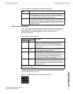
Caution: Do not operate the FortiGate-5140 chassis with open slots on the front panel. For
optimum cooling performance and safety, the slots must contain a FortiGate-5000 series
board or an air baffle slot filler. As well the removable terminal block cover must be installed
over the power connectors on the back of the chassis.