AT91SAM7L-STK Rev. A Starter Kit User Guide i
6409A–ATARM–30-Jun-08
Table of Contents
Section 1
Overview ....................................................................................................................1-1
1.1 Scope................................................................................................................................. 1-1
1.2 Deliverables ...................................................................................................................... 1-1
1.3 The AT91SAM7L-STK Rev. A Starter Board..................................................................... 1-1
Section 2
Setting Up the AT91SAM7L-STK Rev. A Board.........................................................2-1
2.1 Electrostatic Warning......................................................................................................... 2-1
2.2 Requirements..................................................................................................................... 2-1
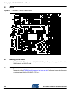
2.3 Layout ................................................................................................................................ 2-2
2.4 Powering Up the Board...................................................................................................... 2-2
2.5 Getting Started................................................................................................................... 2-2
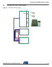
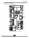
2.6 AT91SAM7L-STK Rev. A Block Diagram .......................................................................... 2-3
Section 3
Board Description.......................................................................................................3-1
3.1 AT91SAM7L64/128 Microcontroller................................................................................... 3-1
3.2 AT91SAM7L64/128 Block Diagram ................................................................................... 3-3
3.3 Memory.............................................................................................................................. 3-4
3.4 Clock Circuitry.................................................................................................................... 3-4
3.5 Reset Circuitry ................................................................................................................... 3-4
3.6 Shut Down controller.......................................................................................................... 3-4
3.7 Power Supply Circuitry.......................................................................................................3-4
3.8 User Interface .................................................................................................................... 3-4
3.9 Debug Interface ................................................................................................................. 3-4
3.10 Expansion Slot................................................................................................................... 3-4
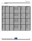
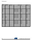
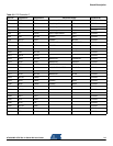
3.11 PIO Usage ......................................................................................................................... 3-5
Section 4
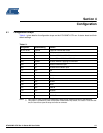
Configuration ..............................................................................................................4-1
4.1 Configuration Straps .......................................................................................................... 4-1
Section 5
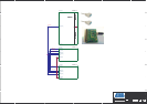
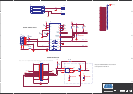
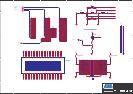
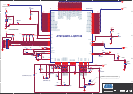
Schematics.................................................................................................................5-1
Section 6
Errata..........................................................................................................................6-1