Board Description
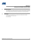
3-2 AT91SAM7L-STK Rev. A Starter Kit User Guide
6409A–ATARM–30-Jun-08
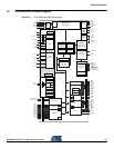
• Debug Unit (DBGU)
– Two-wire UART and Support for Debug Communication Channel interrupt, Programmable ICE Access
Prevention
• Periodic Interval Timer (PIT)
– 20-bit Programmable Counter plus 12-bit Interval Counter
• Windowed Watchdog (WDT)
– 12-bit Key-protected Programmable Counter
– Provides Reset or Interrupt Signals to the System
– Counter may be Stopped While the Processor is in Debug State or in Idle Mode
• Real-time Clock (RTC)
– Two Hundred Year Calendar with Alarm
– Runs Off the Internal RC or Crystal Oscillator
• Three Parallel Input/Output Controllers (PIOA, PIOB, PIOC)
– Eighty Programmable I/O Lines Multiplexed with up to Two Peripheral I/Os
– Input Change Interrupt Capability on Each I/O Line
– Individually Programmable Open-drain, Pull-up resistor and Synchronous Output
• Eleven Peripheral DMA Controller (PDC) Channels
• One Segmented LCD Controller
– Display Capacity of Forty Segments and Ten Common Terminals
– Software Selectable LCD Output Voltage (Contrast)
• Two Universal Synchronous/Asynchronous Receiver Transmitters (USART)
– Individual Baud Rate Generator, IrDA
®
Infrared Modulation/Demodulation
– Support for ISO7816 T0/T1 Smart Card, Hardware Handshaking, RS485 Support
– Manchester Encoder/Decoder
– Full Modem Line Support on USART1
• One Master/Slave Serial Peripheral Interface (SPI)
– 8- to 16-bit Programmable Data Length, Four External Peripheral Chip Selects
• One Three-channel 16-bit Timer/Counter (TC)
– Three External Clock Inputs, Two Multi-purpose I/O Pins per Channel
– Double PWM Generation, Capture/Waveform Mode, Up/Down Capability
• One Four-channel 16-bit PWM Controller (PWMC)
• One Two-wire Interface (TWI)
– Master, Multi-Master and Slave Mode Support, All Atmel
®
Two-wire EEPROMs and I
2
C compatible
Devices Supported
– General Call Supported in Slave Mode
• One 4-channel 10-bit Analog-to-Digital Converter, Four Channels Multiplexed with Digital I/Os
• SAM-BA
®
Boot Assistant
– Default Boot Program
– Interface with SAM-BA Graphic User Interface
– In Application Programming Function (IAP)
• IEEE
®
1149.1 JTAG Boundary Scan on All Digital Pins
• I/Os, including Four High-current Drive I/O lines, Up to 4 mA Each
• Power Supplies
– Embedded 1.8V Regulator, Drawing up to 60 mA for the Core with Programmable Output Voltage
– Single Supply 1.8V - 3.6V
– Zero-power Power-on Reset and Brownout Detector, Fully Programmable
• Fully Static Operation: Up to 36 MHz at 85°C
• Available in a 128-lead LQFP Green and a 144-ball LFBGA Green Package