


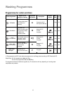


25
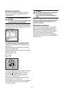
Building-in
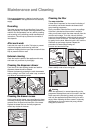
This appliance has been designed to be built into the
kitchen furniture.
The recess should have the dimensions shown in
picture A.
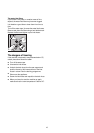
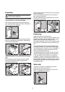
Preparation and assembly of the door
The machine is originally pre-arranged for the assembly
of a door opening from right to left.
In this case it is sufficient to screw in the hinges (1) and
the counter-magnet (6) provided with the appliance, at
the right level (Fig. B).
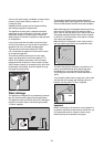
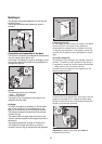
a) Door
The dimensions of the door should be:
- width 595-598 mm
- thickness 16-22 mm
The height (C-Fig. C) depends on the height of the
adjacent furniture's base.
b) Hinges
To mount the hinges it is necessary to drill two holes
(dia. 35 mm, depth 12.5-14 mm depending on the
depth of door furniture) on the inner side of the door.
The distance between the holes hobs fixing centres
must be 416 mm.
The distance (B) from upper edge of the door to the
centre of the hole depends on the adjacent furniture's
dimensions.
The required dimensions are given in the picture C.
The hinges will be fixed to the door by means of
screws for wood (2-Fig. B) supplied with the appliance.
4
1
2
3
6
1
2
3
P0982
7
8
B
5
P0965
820 min
570 min.
600
596
416
176,5
818
541
195
490
160
120
90
8
515
165
A
600
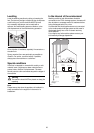
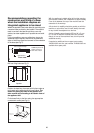
c) Mounting the door
Fix the hinges (1) to the machine by means of the M5x8
screws (3-Fig. B). The hinges can be adjusted to
compensate for possible uneven thickness of the door.
To align the door perfectly it is necessary to loosen the
screw (3-Fig. B), adjust the door and tighten the screw
again.
d) Counter-magnet (6)
The appliance is pre-arranged for a magnetic closure of
the door. To enable a correct operation of this device, it
is necessary to screw the counter-magnet (6) (steel disk
+ rubber ring) into the inner side of the door.
Its position must correspond to the magnet (4) on the
appliance (see picture D).
If the door has to be opened from left to right, invert the
position of the plates (7), the magnet (4) and the plate
(5) (Fig. B and E). Mount the countermagnet (6) and the
hinges (1) as previously described.
Important: the plastic screw (8) should never be
loosened (Fig. B and E).
4
6
5
1
2
3
7
8
E
P0983
P0984
6
4
8
D
35 Ø 12.5-14 depth
16-22
B
C
22+1,5
595-598
416
P0422S
C