


3
Location Requirements
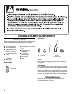
You will need
■ A location that allows for proper exhaust installation. See
“Venting Requirements.”
■ A separate 30-amp circuit.
■ If you are using a power supply cord, a grounded electrical
outlet located within 2 ft (610 mm) of either side of the dryer.
See “Electrical Requirements.”
■ A sturdy floor to support the total dryer weight of 200 lbs
(90.7 kg). The combined weight of a companion appliance
should
also be considered.
■ A level floor with a maximum slope of 1" (25 mm) under entire
dryer. If slope is greater than 1" (25 mm), install Extended Dryer
Feet Kit, Part Number 279810. Clothes may not tumble properly
and automatic sensor cycles may not operate correctly if dryer is
not level.
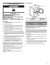
■ For a garage installation, you will need to place the dryer at least
18" (460 mm) above the floor. If using a pedestal, you will need
18" (460 mm) to the bottom of the dryer.
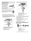
■ Steam models only: Cold water faucets located within 4 ft
(1.2 m) of the dryer, and water pressure of 20-100 psi
(137.9-689.6 kPa). You may use the cold water supply from
your washer using the “Y” connector provided.
Do not operate your dryer at temperatur
es below 45ºF (7ºC). At
lower temperatures, the dryer might not shut off at the end of an
automatic sensor cycle. This can result in longer drying times.
The dryer must not be installed or st
ored in an area where it will
be exposed to water and/or weather.
Check code requirements. Some codes limit, or
do not permit,
installation of the dryer in garages, closets, mobile homes, or
sleeping quarters. Contact your local building inspector.
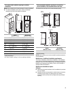
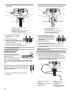
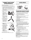
Installation clearances
The location must be large enough to allow the dryer door to
open fully.
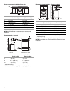
Dryer Dimensions
A
B
C
D
Steam
(Electric or Gas)
Non-Steam
(Electric or Gas)
A 38" (9652 mm) 38" (9652 mm)
B 32
9
/16" (686 mm) 31
1
/2" (800 mm)
C 27" (686 mm) 27" (686 mm)
D 52
9
/16" (1335 mm) 51
1
/2" (1308 mm)
NOTE: Most installations r
equire a minimum 5" (127 mm) clearance
behind the dryer for the exhaust vent with elbow.
See “Venting Requirements.”
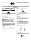
Installation spacing for recessed area or closet installation
The following spacing dimensions are recommended for this dryer.
This dryer has been tested for spacing of 0" (0 mm) clearance on the
sides an
d rear. Recommended spacing should be considered for the
following reasons:
■ Additional spacing should be considered for ease of installation
and servicing.
■ Additional clearances might be required for wall, door, and floor
moldings.
■ Additional spacing should be considered on all sides of the dryer
to reduce noise transfer.
■ For closet installation, with a door, minimum ventilation openings
in the top and bottom of the door are required. Louvered doors
with equivalent ventilation openings are acceptable.
■ Companion appliance spacing should also be considered.