


10
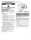
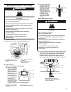
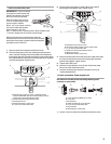
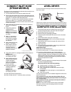
2. Connect neutral wire (white or center wire) of power supply cord
to the center silver-colored terminal screw of the terminal block.
Tighten screw.
A
B
C
D
E
A.External ground conductor screw
B. Neutral ground wire
C. Center silver-colored terminal block screw
D. Neutral wire (white or center wire)
E. ¾" (19 mm) UL listed str
ain relief
3. Connect the other wires to outer
terminal block screws. Tighten
screws.
4. Tig
hten strain relief screws.
5. Insert tab of terminal block cover into
slot of dryer rear panel. Secure cover
with hold-down screw.
6. Y
ou have completed your electrical
connection. Now go to “Venting Requirements.”
3-wire connection: Direct wire
Use where local codes permit
connecting cabinet-ground
conductor to neutral wire.
Direct wire cable must have 5 ft
(1.52 m) of extra length so dryer can
be moved if needed.
Strip 3
1
/2" (89 mm) of outer covering
from end of cable. Strip insulation
back 1" (25 mm). If using 3-wire cable with ground wire, cut bare
wire even with outer covering. Shape ends of wires into a hook
shape.
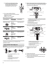
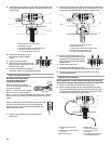
When connecting to the terminal block, place the hooked
end of the wire under the screw of the terminal block
(h
ook facing right), squeeze hooked end together and
tighten screw, as shown.
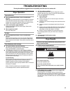
1. Loosen or r
emove center silver-colored terminal
block screw.
2. Place the hooked end of th
e neutral wire (white or center wire) of
direct wire cable under the center screw of terminal block (hook
facing right). Squeeze hooked end together. Tighten screw.
A
C
D
B
E
A. External ground conductor screw
B. Neutral ground wire
C. Center silver-colored terminal block screw
D. Neutral wire (white or center wire)
E. ¾" (19 mm) UL listed strain relief
3. Place the hooked ends of the other
direct wire cable wires under the outer
terminal block screws (hooks facing
right). Squeeze hooked ends together.
Tighten screws.
4. T
ighten strain relief screw.
5. I
nsert tab of terminal block cover into
slot of dryer rear panel. Secure cover with hold-down screw.
6. Y
ou have completed your electrical connection. Now go to
“Venting Requirements.”
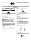
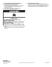
Optional 3-wire connection
Use for direct wire or power supply cord where local codes do
not permit connecting cabinet-ground conductor to neutral wire.
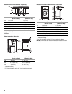
1. Remo
ve center silver-colored terminal block screw.
2. Remove neut
ral ground wire from external ground conductor
screw. Connect neutral ground wire and the neutral wire (white
or center wire) of power supply cor
d/cable under center, silver-
colored terminal block screw. Tighten screw.
A.External ground conductor
screw
B. Center silver-colored terminal
blo
ck screw
C.Neutral ground wire
D. Neutral wire
(white or center wire)
E. ¾" (19 mm) UL listed
strain relief
F. Grounding path determined
by a quali
fied electrician
A
B
C
D
F
E
1"
(25 mm)
3½"
(89 mm)