


Multiple Dryer Venting
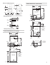
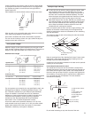
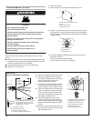
■ A main vent can be used for venting a group of dryers. Main
vent should be sized to remove 200 CFM of air per dryer.
Large-capacity lint screens of proper design may be used in
the main vent if checked and cleaned frequently. The room
where the dryers are located should have make-up air equal
to or greater than the CFM of all the dryers in the room.
■ Back-draft Damper Kits, Part No. 3391910, are available from
your Whirlpool dealer and should be installed in each dryer's
vent to prevent exhausted air from returning into the dryers
and to keep the exhaust in balance within the main vent.
Unobstructed air openings are required.
Each vent should enter the main vent at an angle pointing in the
direction of the airflow. Vents entering from the opposite side
should be staggered to reduce the exhausted air from interfering
with the other vents.
The maximum angle of each vent entering the main vent should
be no more than 30°.
Keep air openings free of dry cleaning fluid fumes. Fumes create
acids which, when drawn through the dryer heating units, can
damage dryers and loads being dried.
A clean-out cover should be located on the main vent for periodic
cleaning of the vent system.
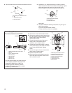
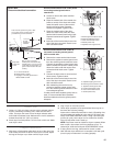
If an exhaust hood cannot be used:
The outside end of the main vent should have a sweep elbow
directed downward. If the main vent travels vertically through the
roof, rather than through the wall, install a 180° sweep elbow on
the end of the vent at least 2 feet (61 cm) above the highest part
of the building. The opening wall or roof shall have a diameter ¹⁄₂"
(1.3 cm) larger than the vent diameter. The vent should be
centered in the opening.
Do not install screening or cap over the end of the vent.
If using an existing vent system, clean lint from the entire length
of the system and make sure exhaust hood is not plugged with
lint. Replace any plastic or metal foil vent with rigid metal or
flexible metal vent.
Plan installation to use the fewest number of elbows and turns.
Allow as much room as possible when using elbows or making
turns. Bend vent gradually to avoid kinking.
Vent outlet is located at the center of the bottom dryer back.
The vent can be routed up, down, left, right, behind the dryer or
straight out the back of the dryer.
Vent System Length
Maximum length of vent system depends upon the type of vent
used, number of elbows and type of exhaust hood. The maximum
length for both rigid and flexible vent is shown in the chart.
For vent systems not covered by the vent specification chart, see
Whirlpool Service Manual, “Exhausting Whirlpool Dryers,” Part
No. LIT603197, available from your Whirlpool parts distributor.
If dryer is installed in a confined area, such as a bedroom,
bathroom or closet, provision must be made for enough air for
combustion and ventilation. (Check governing codes and
ordinances.) See “Recessed Area and Closet Installation
Instructions” in the “Location Requiements” section.
A four-inch outlet hood is preferred. However, a 2¹⁄₂" (6.4 cm)
outlet exhaust hood may be used. A 2¹⁄₂" (6.4 cm) outlet creates
greater back pressure than other hood types. For permanent
installation, a stationary vent system is required.
9
A
B
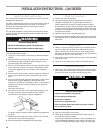
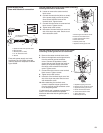
Exhaust Air Flow
A. Better
B. Good
Rigid Metal Vent
No. of 90° turns
No. of 90° turns
Flexible Metal Vent
4" (10.2 cm) Diameter Exhaust Hoods
Maximum Vent Length
64 ft. (19.5 m)
54 ft. (16.5 m)
44 ft. (13.4 m)
35 ft. (10.7 m)
27 ft. (8.2 m)
36 ft. (11.0 m)
31 ft. (9.4 m)
27 ft. (8.2 m)
25 ft. (7.6 m)
23 ft. (7.0 m)
0
1
2
3
4
0
1
2
3
4
58 ft. (17.7 m)
48 ft. (14.6 m)
38 ft. (11.6 m)
29 ft. (8.8 m)
21 ft. (6.4 m)
28 ft. (8.5 m)
23 ft. (7.0 m)
19 ft. (5.8 m)
17 ft. (5.2 m)
15 ft. (4.6 m)
Box Hood and Louvered Style Angled Hood Style
Box Hood and Louvered Style Angled Hood Style
A. Individual dryer vent
B. Main vent
air flow
30° max.
A
B
A
A. Exhaust hood or elbow
B. Wall
C. Main collector vent
D. Horizontal vent
E. 180° sweep elbow
F. Vertical vent
G. Roof
E
B
G
C
D
2 ft. (61 cm) min. above
highest point of building
F
C