


8
■ Installed in a confined area:
If the dryer is installed in a confined area such as a bathroom
or closet, provision must be made for enough air for
combustion and ventilation. Check governing codes and
ordinances or refer to the “Recessed Area and Closet
Installation Instructions” in the “Location Requirements”
section.
Gas Supply Pressure Testing
A ¹⁄₈" NPT minimum plugged tapping, accessible for gauge
testing, must be installed immediately upstream of the gas supply
connection to the dryer.
The dryer must be disconnected from the gas supply piping
system during any pressure testing of the system at test
pressures in excess of ¹⁄₂ psig.
Venting Requirements
WARNING: To reduce the risk of fire, this dryer MUST BE
EXHAUSTED OUTDOORS.
■ The dryer vent must not be connected into any gas vent,
chimney, wall, ceiling, or a concealed space of a building.
■ Do not use an exhaust hood with a magnetic latch.
■ Do not install flexible metal vent in enclosed walls, ceilings or
floors.
■ 4" (10.2 cm) heavy metal vent and clamps must be used.
■ Use clamps to seal all joints. Vent must not be connected or
secured with screws or other fastening devices which extend
into the interior of the vent. Do not use duct tape.
IMPORTANT: Observe all governing codes and ordinances.
Use a heavy metal vent. Do not use plastic or metal foil vent.
Rigid metal vent is recommended to prevent crushing and
kinking.
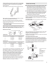
Flexible metal vent must be fully extended and supported when
the dryer is in its final position. Remove excess flexible metal vent
to avoid sagging and kinking that may result in reduced airflow
and poor performance.
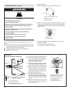
An exhaust hood should cap the vent to prevent rodents and
insects from entering the home or business.
Exhaust hood must be at least 12" (30.5 cm) from the ground or
any object that may be in the path of the exhaust (such as
flowers, rocks or bushes).
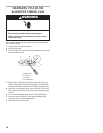
WARNING
Fire Hazard
Use a heavy metal vent.
Do not use a plastic vent.
Do not use a metal foil vent.
Failure to follow these instructions can result in death
or fire.
Flexible metal appliance connector:
■ It is recommended that a new flexible stainless steel gas line,
design-certified by CSA International, be used for connecting
the dryer to the gas supply line. (The gas pipe which extends
through the lower rear of the dryer is provided with ³⁄₈" male
pipe thread.)
■ Do not kink or damage the flexible stainless steel gas line
when moving the dryer.
Rigid pipe connection:
The rigid pipe connection requires a combination of pipe fittings
to obtain an in-line connection to the dryer.
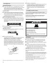
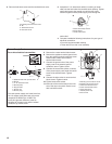
■ Must include a shutoff valve:
The supply line must be equipped with a manual shutoff valve
installed within 6 ft. (1.8 m) of dryer in accordance with
National Fuel Gas Code, ANSI Z223.1. In Canada, an
individual manual shutoff valve must be installed in
accordance with the B149 installation codes CAN/CGA
B149.1 and CAN/CGA B149.2. This valve should be located in
the same room as the dryer. It should be in a location that
allows ease of opening and closing. Do not block access to
shutoff valve. The valve is for turning on or shutting off gas to
the dryer.
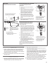
A. Gas supply line
B. Shutoff valve “open” position
C. To dr
y
er
A
B
C
Gas Supply Line
Recommended method
■ Provide a gas supply line of ¹⁄₂" rigid (IPS) pipe to the dryer
location. Pipe joint compounds that resist the action of LP gas
must be used. Do not use TEFLON
®†
tape. With LP gas,
piping or tubing size can be ¹⁄₂" minimum. Usually, LP gas
suppliers determine the size and materials used in the system.
Alternate method
■ The gas supply may also be connected using ³⁄₈" approved
copper or aluminum tubing. If the total length of the supply
line is more than 20 feet (6.1 m), larger tubing will be required.
If using natural gas, do not use copper tubing. Pipe joint
compounds that resist the action of LP gas must be used.
†®TEFLON is a registered trademark of E.I. Du Pont De Nemours and Company.