


10
3.
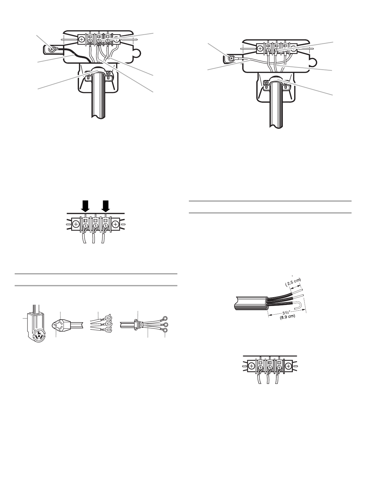
Connect ground wire (green or bare) of power supply cable to
external ground conductor screw. Tighten screw.
4.
Place the hooked end of the neutral wire (white wire) of power
supply cable under the center screw of terminal block (hook
facing right). Squeeze hooked end together. Tighten screw.
5.
Place the hooked ends of the other power supply cable wires
under the outer terminal block screws (hooks facing right).
Squeeze hooked ends together. Tighten screws.
6.
Tighten strain relief screws.
7.
Insert tab of terminal block cover into slot of dryer rear panel.
Secure cover with hold-down screw.
3-wire connection: Power supply cord
Use where local codes permit connecting cabinet-ground
conductor to neutral wire.
1.
Loosen or remove center terminal block screw.
2.
Connect neutral wire (white or center wire) of power supply
cord to the center, silver-colored terminal screw of the
terminal block. Tighten screw.
3.
Connect the other wires to outer terminal block screws.
Tighten screws.
4.
Tighten strain relief screws.
5.
Insert tab of terminal block cover into slot of dryer rear panel.
Secure cover with hold-down screw.
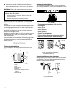
3-wire connection: Direct wire
Use where local codes permit connecting cabinet-ground
conductor to neutral wire.
Direct wire cable must have 5 ft (1.52 m) of extra length so dryer
can be moved if needed.
Strip 3
¹⁄₂
in. (8.9 cm) of outer covering from end of cable. Strip
insulation back 1 in. (2.5 cm). If using 3-wire cable with ground
wire, cut bare wire even with outer covering. Shape ends of wires
into a hook shape.
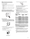
When connecting to the terminal block, place the hooked end of
the wire under the screw of the terminal block (hook facing right),
squeeze hooked end together and tighten screw. See example
below.
1.
Loosen or remove center terminal block screw.
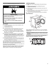
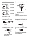
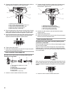
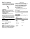
1. External ground conductor screw
2. Green or bare copper wire of power supply cord
3.
³⁄₄
in. (1.9 cm) UL listed strain relief
4. Center silver-colored terminal block screw
5. Neutral grounding wire (green/yellow)
6. Neutral wire (white or center wire)
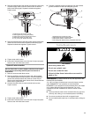
1. 3-wire receptacle (NEMA type 10-30R)
2. 3-wire plug
3. Neutral prong
4. Spade terminals with up turned ends
5.
³⁄₄
in. (1.9 cm) UL listed strain relief
6. Ring terminals
7. Neutral (white or center wire)
1
2
3
4
5
6
1
2
4
3
5
6
7
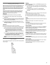
1. External ground conductor screw
2. Neutral grounding wire (green/yellow)
3. Center silver-colored terminal block screw
4. Neutral wire (white or center wire)
5.
³⁄₄
in. (1.9 cm) UL listed strain relief
1
2
3
4
5
1