


GB
7
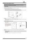
3.3 ADDITIONAL IMPORTANT INSTALLATION INSTRUCTIONS
1. Caref ully read the installation instructions in point 3 on page 6 of the washer dryer installation manual.
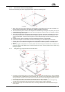
2. After the initial instructions have been adhered to. I.e. remov ing transit bolts and fitting the adjustable feet etc.
Using a spirit level, make sure that the washer dryer is completely lev el and the overall height of the legs, in-
cluding the rubber foot and the locking nuts, is no greater than 25mm maximum.
3. When installing the washer dry er y ou must ensure that the leg locking nuts are firmly tightened.
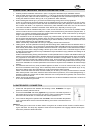
Under no circumstances should the washer dry er be installed with the front legs higher than the rear. If atten-
tion is required in lev elling the f urniture door then we would adv ise fitting the “push-push” catch and the rub-
ber f urniture door buffer. It is important to note that any other installation other than one of a lev el nature
could induce v ibration or excessive movement of the washer dry er, especially on the spin cycle.
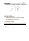
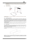
4. The machine should be installed directly onto a clean, sound and level f loor, and as low as possible. Please
note this machine should not be installed on carpets, f oam-backed f looring, laminate and parquet floors. If,
however, f or cosmetic purposes the machine height needs to be raised, it must not be done so by raising the
height of the legs, but via an additional baseboard.
As a manufacture we do not recommend or specify any particular means by which to raise the washer dryer,
but hav e found that dense board, between 18mm and 40mm in thickness, grip-fixed and screwed to the f loor
and capable of supporting the weight of the washer dryer without distortion, and cut to the dimensions of the
machine base appears to be good installation practice.
Please note that any material that has a shiny or a slippery f inish should not be used.
5. Floating floors. As more apartments are being built with f loating f loors, additional care must be taken when in-
stalling the washer dryers. The current flooring specif ications state that additional bracing must be installed in
areas directly below electric storage heaters and door thresholds. It is important to note that whilst some elec-
tric storage heaters have a weight of 80kgs, washer dry ers, when loaded, hav e a combined weight in excess
of 90kgs and the oscillating nature of any loaded washer dry er will deliv er v arying stresses and loadings on to
the adjacent floor area.
However because floating flooring manuf acturers current specifications do not state that additional bracing is
required in the f loor area below heavy domestic appliances the f looring area below washer dryers is generally
only supported in one direction and not two as is the case with electric storage heaters. Theref ore in order to
prov ide the house purchaser with additional peace of mind, and to prevent any unnecessary v ibration and os-
cillation in the kitchen area we would adv ise house builders to consider f itting additional f loor bracing at the
time of floor installation to a similar specification to that which is required f or the installation of electric storage
heaters.
6. The ideal base surf ace f or any heavy domestic appliance to stand on is one of solid concrete, as any minor
leak f rom the domestic water supply will not adv ersely effect the area adjacent to the washer dry er, as any
leak onto a floating and/or wood laminate floor could cause extensive water damage.
Please note that as these machines are water tested prior to leav ing our f actory a small amount of residual
water will be present in the hoses, theref ore care must be taken to prevent any minor water spillage during in-
stallation. Please also ensure that the water f eed hose are correctly fitted and tightened, both at the mains
and the machine connectors.
7. Please ensure that installation is carried out in accordance to the above installation instructions. As failure to
do so could invalidate the guarantee.
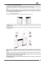
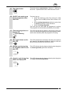
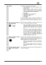
3.4 WATER SUPPLY CONNECTION
1. Check that inlet pressure lies between the f ollowing v alues: 50-900kPa. For higher
pressures, install a pressure reducer.
2. Connect the cold water inlet hose (light blue ring nut) to the cold water tap with a ¾
gas thread, taking care to screw it firmly into place in order to prevent leaks. The water
inlet hose must not be bent or crushed and must not be replaced or cut.
3. If the model is designed f or operation with hot water, then the inlet water temperature
must not exceed 60°C and the hose with the red ring nut must be connected to the hot
water tap.
Attention!
• If the water pipe is new or has not been used f or a long time, let a certain amount of water run bef ore attach-
ing the inlet hose. This stops any deposits of sand and other impurities from clogging the f ilters used by the
machine to protect the water inlet v alves.