


97-6068, 97-6131 • REV. 3/06
19
PRESSURE WASHER
OPERATOR’S MANUAL
MAINTENANCE
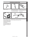
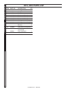
Electrodes Check: Periodically check wiring connections.
If necessary to adjust electrodes, use diagram.
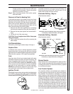
5/32" Gap
5/16"
Side View
1/16"
Top View
Electrode
Nozzles
through pressure washer and into HPB coils
and back into the bucket. Solution should be
allowed to circulate 2-4 hours.
Step 4 After circulating solution flush entire system
with fresh water.
Removal of Soot In Heating Coil:
In the heating process, fuel residue in the form of soot
deposits may develop between the heating coil pipe
and block air flow which will affect burner combustion.
When soot has been detected on visual observation,
the soot on the coil must be washed off after coil has
been removed using the following steps:
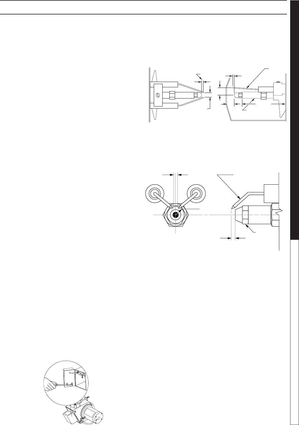
1. Remove the tank head assembly by unscrewing
the three tek screws and lifting the tank head off.
2. Remove the two pipe nipples and associated fit-
tings.
3. Lift the coil out of the outer wrap.
CAUTION: The coil weighs about 80 lbs. Use proper
lifting techniques.
4. Clean, repair and replace the coil by reversing the
above steps.
Coil Reinstallation
Reinstall by reversing the above steps 4 through 1.
Rupture Disk
If pressure from pump or thermal expansion should
exceed safe limits, the rupture disk will burst, allowing
high pressure to be discharged through hose to ground.
When the disk ruptures, it will need to be replaced.
Fuel:
Use clean fuel oil that is not contaminated with water
and debris. Replace fuel filter and drain tank every 100
hours of operation. Use Kerosene No. 1 or No. 2 Heat-
ing Fuel (ASTM D306) or diesel only. NEVER use gaso-
line in your burner tank. Gasoline is more combustible
than fuel oil and could result in a serious explosion.
NEVER use crankcase or waste oil in your burner. Fuel
unit malfunction could result from contamination.
Ignition Circuit:
Periodically inspect wires, spring contact and electrodes
for condition, security and proper spacing. For trans-
former test (CAUTION 10,000 VOLTS) use defect free
insulated screwdriver and keep fingers off blade! Lay
blade across one contact: OK if arc will span 1/2" be-
tween end of blade and other contact.
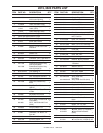
Electrode Setting - Wayne:
(See illustration below)
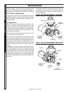
Electrode Setting - Beckett:
(See illustration below)
Burner Nozzle:
Keep the tip free of surface deposits by wiping it with a
clean, solvent-saturated cloth, being careful not to plug
or enlarge the nozzle. For maximum efficiency, replace
the nozzle each season.
Fuel Control System:
This machine utilizes a fuel solenoid valve located on
the fuel pump to control the flow of fuel to the combus-
tion chamber. This solenoid is activated by a pressure
switch located on the unloader valve. When an operator
releases the trigger on the spray gun, the pressure drops,
allowing the pressure switch to activate the fuel sole-
noid. The solenoid then closes, shutting off the supply of
fuel to the combustion chamber. Controlling the flow of
fuel in this way gives an instantaneous burn or no burn
situation, thereby eliminating high and low water tem-
peratures, and combustion smoke normally associated
with machines incorporating a spray gun. Periodic inspec-
tion is recommended to insure that the fuel solenoid valve
Electrodes Check: Periodically check wiring connections.
If necessary to adjust electrodes, use diagram.
Gap
1/8"
3/16"
Side View
1/8"
3/8"
1/2"
Electrodes
Nozzle
Adapter
Top View
2-7/8"