


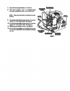
34 13o Connect thet_ack(6M)wke leadOntothe lie" terminal
marked "6" onthe motorswitch_,-'_eFigure.3.
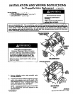
Positionmotoras shown in Figure 2. Notethe location
of the motor switch.Secure motor to bradder with the
origim_ motor damps,
.yVIRING INSTRUCTIONS
NOTE: Read =rid follow Instructions carefully. If the
unit you are replacing the motor on has the option
which included the momentary switches for the drum,
proceed to section title WlRIN_3JNSTRUCTIONS---
MOMENTARY SWITCH APPUCATIONt otherwise,
proceed to s_ep 4.
_,_ Connect the blue (4M) wire lead from the broken belt
switch to the vacant terminal located on the ba_ of
the overload prote_or of _he motor switch. See
Figure 3
5o ConneCt the red (1M) wire lead. to 'Jle _/4_ terminal
marked "1" onthe motor switch. 'See Figure 3.
BLACK "fELLOW,
RGURE3
14. Reconnectgroundwire to motor. _ee Figure 3_
"_5.All wire lead (_nnections are completeat this point.
you can now reinstall the motor andbracket assembly
into the unit.
WIRING INSTRUCTION_
MOMENTARY SWITCH APPLICATION
1_ Connect the blue (4M) wire lead from the broken belt
switchtO the vacantterminal located on the back of
the overload protector of the meter switch. See
Figure 4.
6o Connect the red (2M} wire lead to the _/4"terminal
rr_xked "2" onthe motor sv#ftch.See _Tgure3.
"7. Connect the yellow (BK2) wire lead to the vacant
termth_J onthe broken belt switch. See Figure 3.
8. 'To connect the black (6M} wire lead and the while
(5M) wire lead to the motor switch, you must replace
the _/4"female terminalswiththe 1/8" insulated female
_erminals includedwith the replacement motor.
9_ Cut _e _14'female terminal from the black (6M) and
white (SM) wire leads as close to the terminaJ as
possible with wire eL,tiers.
! O_Strip wires back approxim_,tely _14elan inch.
t"_[h barrel c_mpers, crimp _!_ insulated female:
terminals, ]no4t_dedwith motor, onto the w&'eleads.
2_
4_
,5.
Connect the red (1M} wire lead to the _/4°tem]ina!
m_ked "I" on the motor switch. See Figure 4.
Connect the red (2M) wire lead ta the _14"terminal
markeO "2" on the meier switch. See Figure 4.
Connect the yellow (8K2) wire lead to the vacant
terminal on the broken belt switch See Figure 4.
To connect the purple (3M_ wire lead and the white
(5_'_ wire lead to the motor switch, you must replace
lll e _/4"female terrninalwith the t Is"insulated terminals
included wffhthe replacementmotor.
_f.'_TE: _ake sure ter_r_inals 8_'ecr_rr_dseeurely
_mp_aoe.
2_Connec_ the white (5M) wlre lead onto _he_/e"termi_al .
m_rked "5" on the motor sw_teh See Figure 3
Cut the t/_,, female terminaJ from the purple (3M) and
white (5M) wire leads as close to the terminal as
possible w_h wire cutters
27£788-A .... 2